Vehicle rotating motor

A technology for rotating electrical machines and vehicles. It is used in the manufacture of motor generators, electromechanical devices, and electrical components. It can solve problems such as excessive temperature rise, and achieve the advantages of shortening length, suppressing excessive temperature rise, and suppressing resistance and copper loss. Effect

Inactive Publication Date: 2011-06-15
MITSUBISHI ELECTRIC CORP
View PDF5 Cites 27 Cited by
  • Summary
  • Abstract
  • Description
  • Claims
  • Application Information

AI Technical Summary

Problems solved by technology

However, since the axial lengths of the respective coil ends are approximately equal, there is a disadvantag

Method used


Image

  • Vehicle rotating motor
  • Vehicle rotating motor
  • Vehicle rotating motor

Examples


Embodiment approach 1

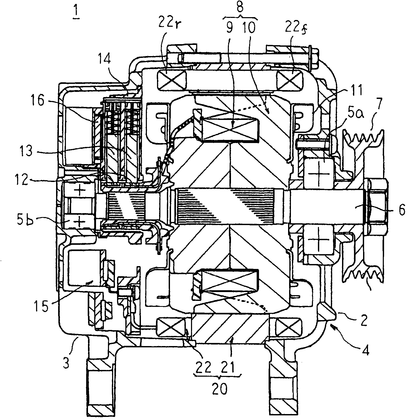
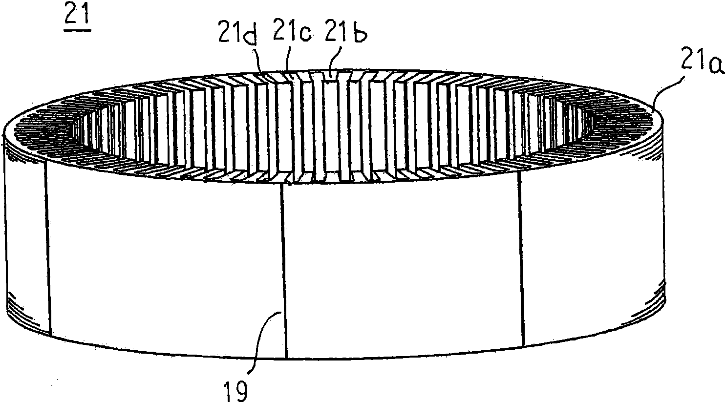
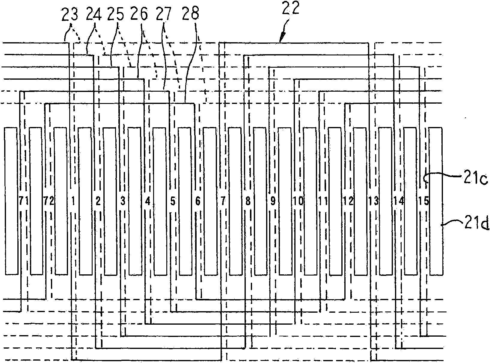
[0063] figure 1 is a longitudinal sectional view showing the automotive alternator according to Embodiment 1 of the present invention, figure 2 It is a perspective view showing a stator core of the automotive alternator according to Embodiment 1 of the present invention. image 3 It is a schematic view explaining the winding state of the stator winding of the automotive alternator according to Embodiment 1 of the present invention, and is a view of the front end of the T-shaped core portion of the stator core viewed from the radially inner side. Figure 4 It is a schematic diagram illustrating the winding state of the stator winding of the automotive alternator according to Embodiment 1 of the present invention, and is a view of one axial end surface of the stator core viewed from the axially outer side. Figure 5 It is a perspective view illustrating the structure of the a-phase winding constituting the stator winding of the automotive alternator according to Embodiment 1 o...

Embodiment approach 2

[0101] Figure 12 It is a sectional view showing a stator of an automotive alternator according to Embodiment 2 of the present invention.

[0102] Figure 12 Among them, the coil end portion 32 of the distribution winding wound on the outer peripheral side of the slot 21c is bent radially inward, and is located on the axially outer side of the coil end portion 32 of the distribution winding wound on the inner peripheral side of the slot 21c. s position.

[0103] In addition, other structures are the same as those of the first embodiment described above.

[0104] Therefore, also in this second embodiment, the same effect as that of the above-mentioned first embodiment can be achieved.

[0105] According to Embodiment 2, since the coil end portion 32 of the distribution winding wound on the outer peripheral side of the slot 21c is bent radially inward, it is located close to the coil end portion of the distribution winding wound on the inner peripheral side of the slot 21c. ...

Embodiment approach 3

[0107] In the third embodiment, the varnish is permeated into the front coil end group 22f and the rear coil end group 22r, and the coil ends 32 are fixed to each other.

[0108] In addition, other configurations are the same as those of Embodiment 1 and Embodiment 2 above.

[0109] According to the third embodiment, since the varnish is permeated into the front coil end group 22f and the rear coil end group 22r, and the coil ends 32 are fixed to each other, the front coil end group 22f and the rear coil end group can be improved. The rigidity of the end group 22r. Therefore, it is possible to prevent the front coil end group 22f and the rear coil end group 22r from coming into contact with the front holder 2 and the rear holder 3 due to vibrations and damaging the insulating coating.

[0110] Here, in the third embodiment, the varnish is impregnated into the front coil end group 22f and the rear coil end group 22r, but the impregnating resin is not limited to the varnish, and ...


PUM


Abstract

Disclosed is a vehicle rotating motor, comprising a stator which can not only inhibit the increasing of resistance and copper loss, but also inhibit the temperature of the peripheral coil end from excessively rising. Each phase winding is divided into a first a-phase winding (231), a first f-phase winding (281), a second a-phase winding (232) and a second f-phase winding (282). The first a-phase winding (231) and the first f-phase winding (281) extend in an axial direction in a groove (21c) and extend in a circumferential direction and enters the groove (21c) separating six slots, thereby a conductor wire (30) is winded at the inner periphery of each groove (21c) of the same groove group. The second a-phase winding (232) and the second f-phase winding (282) extend in an axial direction ina groove (21c) and extend in a circumferential direction and enters the groove (21c) separating six slots, thereby a conductor wire (30) is winded at the outer periphery of each groove (21c) of the same groove group. In addition, the axial length of the first a-phase winding (231) and the first f-phase winding (281) is shorter than that of the second a-phase winding (232) and the second f-phase winding (282).

Description

technical field [0001] The present invention relates to a vehicle-use rotating electric machine such as a vehicle-use alternator. Background technique [0002] The stator of an existing automotive alternator includes: a cylindrical stator core arranged in a circumferential direction with a plurality of slots opening to the inner peripheral side; A plurality of windings in each slot group, wherein a slot group is composed of slots with a predetermined number of slots, and each winding is a winding unit made by winding a conductor wire in a predetermined turn, and is installed on a cylindrical stator core. (for example, refer to Patent Document 1). [0003] Here, a method of winding a stator winding of a stator of a conventional automotive alternator will be described. [0004] First, a conductor wire having a circular cross section is wound into a predetermined loop to form a first winding unit, and then a predetermined loop is wound to form a second winding unit. Next, th...

Claims


Application Information

Patent Timeline
IPC IPC(8): H02K1/16H02K3/04H02K3/28
CPCH02K3/12H02K3/28H02K3/34H02K3/38H02K3/48H02K3/50H02K15/0435H02K15/085H02K15/10H02K15/12
Inventor 田中和德
Owner MITSUBISHI ELECTRIC CORP
Why Eureka
Try Eureka