Fluorescent material coating method and substrate prepared by same
A technology of fluorescent material and coating method, applied in the field of substrate coated with fluorescent material, can solve the problems of uneven light mixing, inaccurate color temperature, irregular shape and size of fluorescent powder, etc., and achieve the effect of improving the refractive index
- Summary
- Abstract
- Description
- Claims
- Application Information
AI Technical Summary
Problems solved by technology
Method used
Image
Examples
Embodiment 1
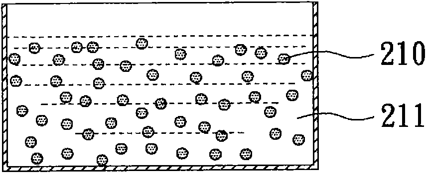
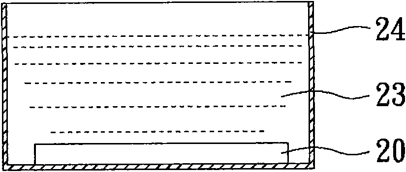
[0030] Figure 2A to Figure 2F It is a schematic diagram of the steps of coating the fluorescent material on the surface of the substrate in Example 1 of the present invention.
[0031] Prepare Phosphor Solution
[0032] First, phosphor powder is taken as a phosphor material, wherein the spherical carrier of the phosphor powder is made of SiO with a particle size of 500nm 2nanospheres, while phosphors use Y particles with a particle size of about 30nm 2 o 3 :La 3+ , YAG: La 3+ And a mixture of CdSe:ZnS, and the phosphor is bonded to the surface of the spherical carrier through silane molecules (APTMS). By adjusting the ratio of various fluorescent powders, after being excited by the blue light-emitting diode, the fluorescent powder can mix light on its surface to emit white light.
[0033] Then, the phosphor powder 210 is mixed in the first solvent 211 with high dispersibility to obtain a phosphor powder mixed solution, such as Figure 2A shown. Here, ethanol is used...
Embodiment 2
[0046] The manufacturing method of this embodiment is as described in Embodiment 1. Wherein, the fluorescent powder used in this embodiment adopts a particle size of 500nm and a material of SiO 2 Nanospheres are used as spherical carriers, while phosphors use Y particles with a particle size of about 50nm 2 o 3 :Eu 3+ , Y 2 o 3 :yb 3+ , Y 2 o 3 : Ce 3+ 、YAG:Ce 3+ And a mixture of CdSe:ZnS, and the mixture of phosphors is contained inside the spherical carrier. In addition, the substrate to be coated in this embodiment is a sapphire substrate. Furthermore, the Al and Ti composite metal alkoxide solution was used as the sol-gel precursor solution, and the La 3+ the Y 2 o 3 Nitric acid solution, undergoing a sol-gel reaction to form a packed layer. Therefore, the filling layer of this embodiment contains Y 2 o 3 :La 3+ Al 2 o 3 -TiO 2 material layer.
Embodiment 3
[0048] The manufacturing method of this embodiment is as described in Embodiment 1. Wherein, the fluorescent powder used in this embodiment adopts a particle size of 1000nm and a material of SiO 2 The nanospheres are used as the spherical carrier, and the spherical carrier contains CdSe:ZnS quantum dots inside; while the phosphor body uses Y with a particle size of about 50nm 2 o 3 :La 3+ and YAG:La 3+ mixture, and the phosphor is bonded to the surface of the spherical carrier through silane molecules.
PUM
 Abstract
Description
Claims
Application Information
 - R&D
- Intellectual Property
- Life Sciences
- Materials
- Tech Scout
- Unparalleled Data Quality
- Higher Quality Content
- 60% Fewer Hallucinations
Browse by: Latest US Patents, China's latest patents, Technical Efficacy Thesaurus, Application Domain, Technology Topic, Popular Technical Reports.
© 2025 PatSnap. All rights reserved.Legal|Privacy policy|Modern Slavery Act Transparency Statement|Sitemap|About US| Contact US: help@patsnap.com


