Air conditioning system
A technology for air conditioning systems and air conditioners, which is applied to heating and ventilation control systems, heating and ventilation safety systems, space heating and ventilation, etc. Failure, low cost, energy saving effect
- Summary
- Abstract
- Description
- Claims
- Application Information
AI Technical Summary
Problems solved by technology
Method used
Image
Examples
Embodiment approach 1
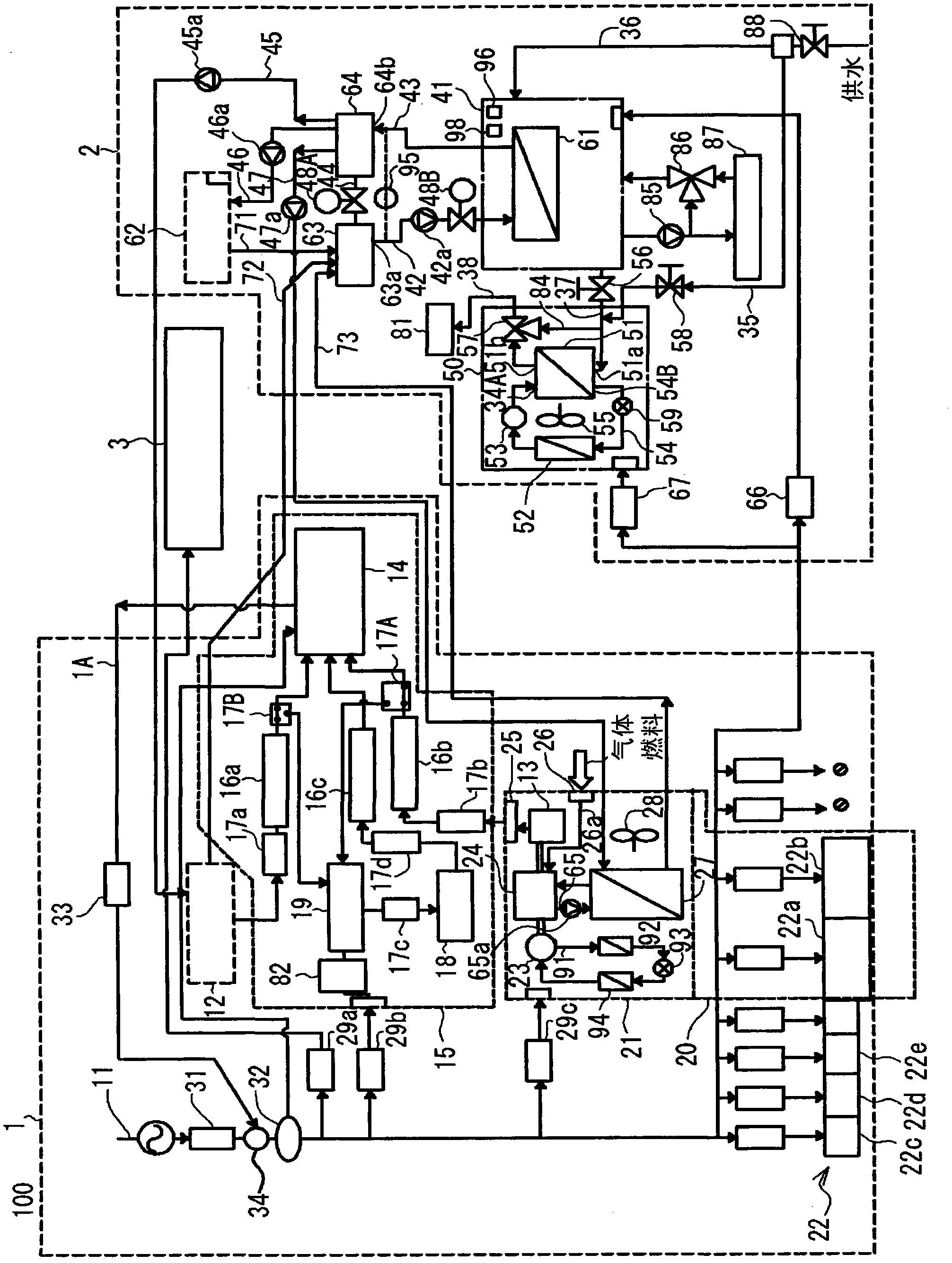
[0084] Such as figure 1 As shown, the air conditioning system 100 of the first embodiment includes an electric power system 1, a warm water system 2, and a system controller 3 that monitors and controls the operating status of each device included in the air conditioning system 100.
[0085] The electric power system 1 includes an industrial power supply system 11 supplied from an electric power company and a plurality of external power generation devices connected to the industrial power supply system 11 in the system. The external power generation device of this embodiment is composed of a photovoltaic power generation device 12 as a DC power generation device, a GHP generator 13 (hereinafter referred to as a generator 13), and a battery 18. The power system 1 is configured to have a PCS (power conditioner. It corresponds to the output circuit of the present invention.) 14 as a device for converting DC power to AC power and superimposing it on wiring. The photovoltaic power gen...
Embodiment approach 2
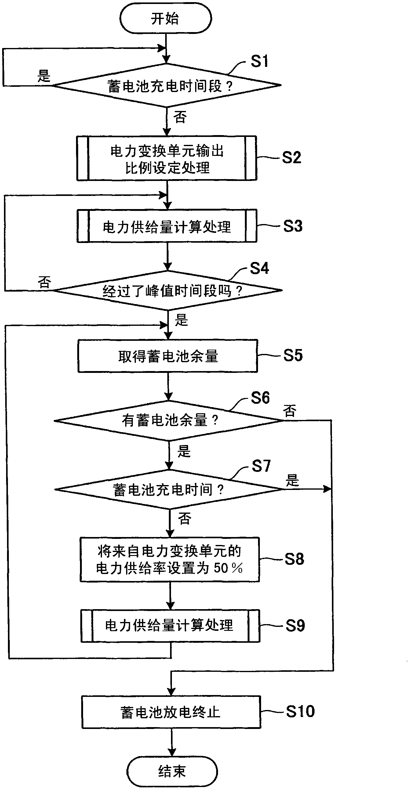
[0136] Next, Embodiment 2 of the present invention will be described. In the first embodiment, the power consumed by the load is detected, the amount of power is compared with the power generated by the generator and the photovoltaic power generation device, and it is determined whether the generated power is charged to the battery or supplied to the load, so that the rechargeable battery can be used efficiently Of electricity. In contrast, in the second embodiment, by predicting in advance the amount of power consumed by the load and the power generated by the generator and the photovoltaic power generation device, the power of the battery can be used efficiently.
[0137] In the air conditioning system of Embodiment 2, since the overall configuration of the air conditioning system of Embodiment 1 is the same, the same reference numerals are used for the same configuration, and detailed descriptions are omitted.
[0138] The system controller 3 of the second embodiment detects th...
Embodiment approach 3
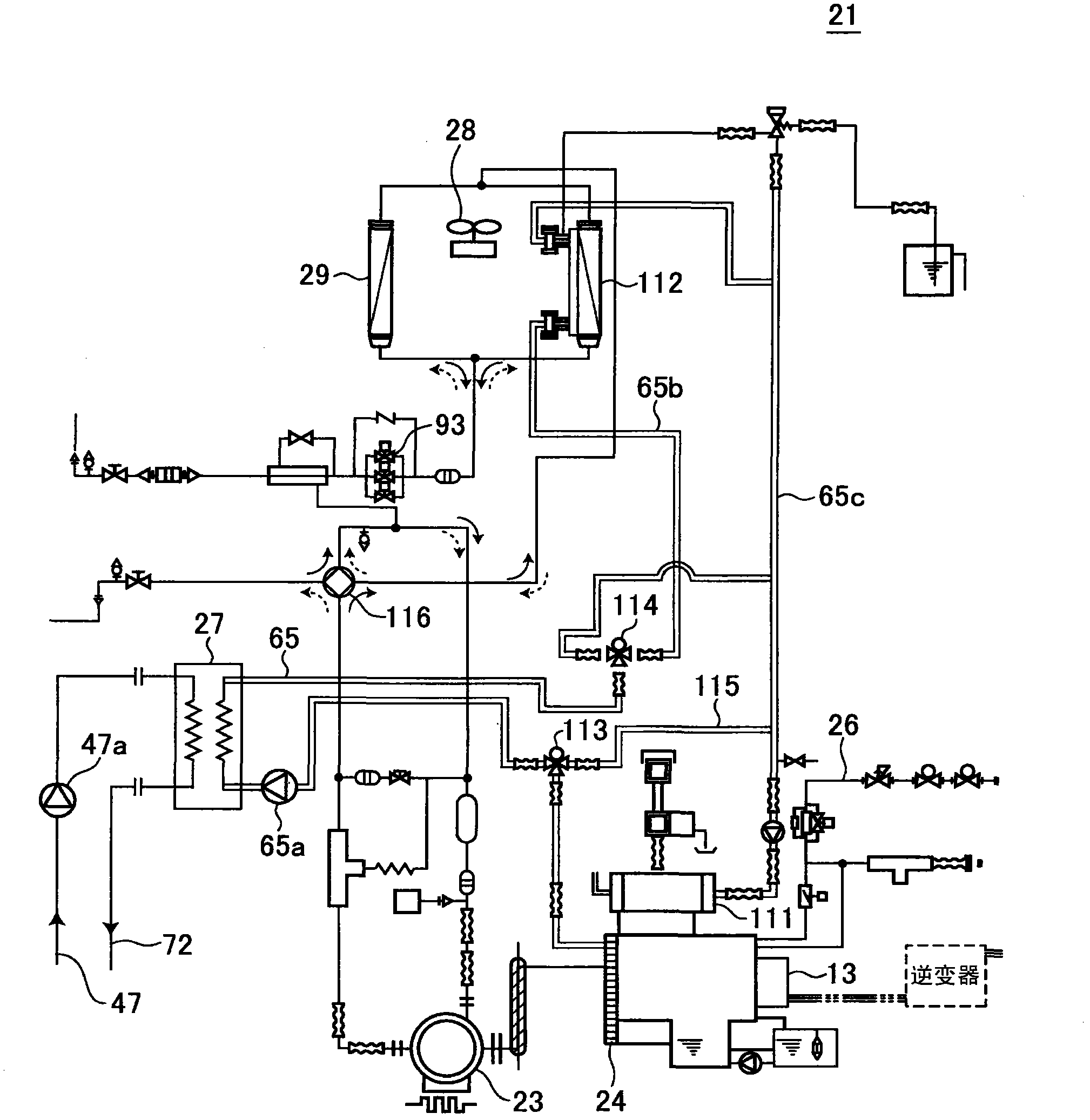
[0167] Next, use Figure 7 ~ Figure 10 The specific configuration of the air conditioners 22a' and 22b' of the third embodiment will be described. The same reference numerals are added to the same structures as the above-mentioned Embodiments 1 and 2, and detailed descriptions are omitted.
[0168] Such as Figure 7 As shown, the air-conditioning system 100 of the third embodiment includes an electric power system 1, a warm water system 2, and a system controller (corresponding to the “control unit” of the present invention) that monitors and controls the operating status of each device included in the air-conditioning system 100 )3.
[0169] The generator 13 is mounted on the outdoor unit 21 of the air conditioner 20. The outdoor unit 21 of the air conditioner 20 includes a gas engine 24 using gas as fuel, a gas pipe 26a for supplying gas to the gas engine 24, and a gas supply port 26 connected to the gas pipe 26a. The gas supply port 26 passes through the gas pipe 26a. The gas ...
PUM
 Abstract
Description
Claims
Application Information
 - R&D
- Intellectual Property
- Life Sciences
- Materials
- Tech Scout
- Unparalleled Data Quality
- Higher Quality Content
- 60% Fewer Hallucinations
Browse by: Latest US Patents, China's latest patents, Technical Efficacy Thesaurus, Application Domain, Technology Topic, Popular Technical Reports.
© 2025 PatSnap. All rights reserved.Legal|Privacy policy|Modern Slavery Act Transparency Statement|Sitemap|About US| Contact US: help@patsnap.com


