Light beam position and polarization angle common light path detection device and method

A polarization angle and detection device technology, which is applied in the direction of measuring devices, optical devices, instruments, etc., can solve the problems that the polarization angle measurement has not been reported.

Active Publication Date: 2011-06-29
SHANGHAI INST OF TECHNICAL PHYSICS - CHINESE ACAD OF SCI
View PDF2 Cites 28 Cited by
  • Summary
  • Abstract
  • Description
  • Claims
  • Application Information

AI Technical Summary

Problems solved by technology

In 2008, Wu Yiming, Gao Limin and Chen Liangyi from the Xi’an Institute of Optics and Mechanics of the Chinese Academy of Sciences discussed the application of modulated polarized light in the transmission of azimuth information. The measurement of polarization angle has not been reported yet [10,11]
[0004] Through the above analysis, it can be found that so far, various ellipsometer ...

Method used


Image

  • Light beam position and polarization angle common light path detection device and method
  • Light beam position and polarization angle common light path detection device and method
  • Light beam position and polarization angle common light path detection device and method

Examples


Embodiment Construction

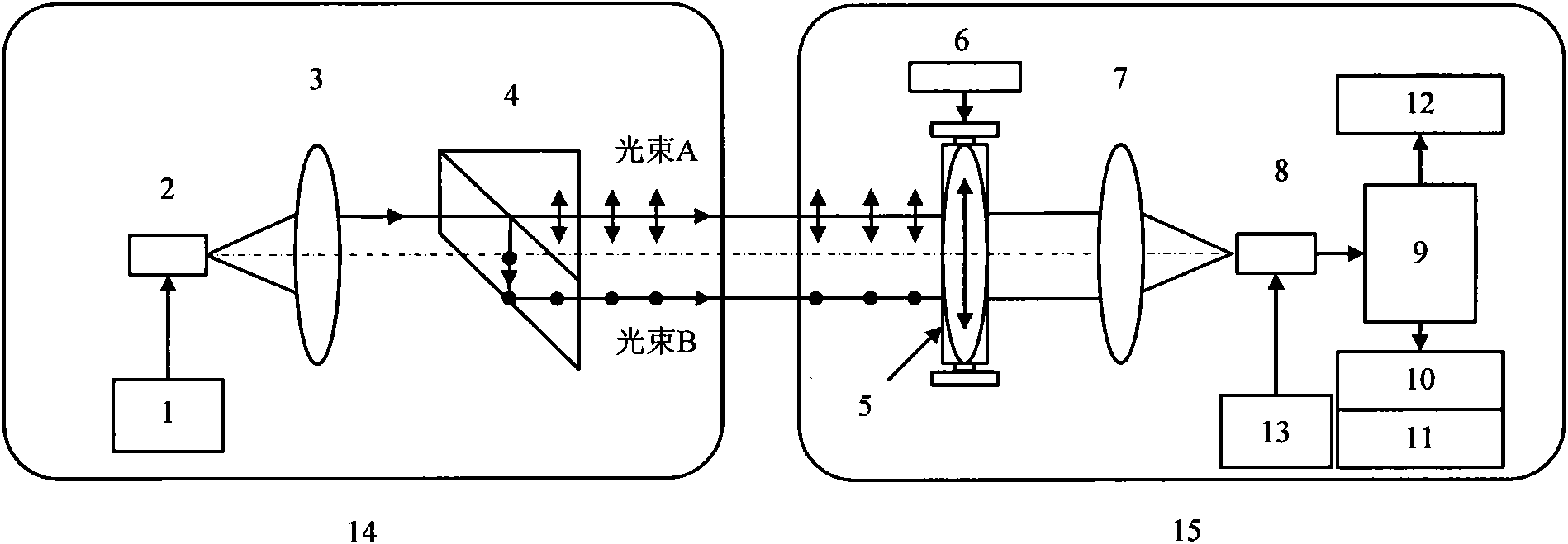
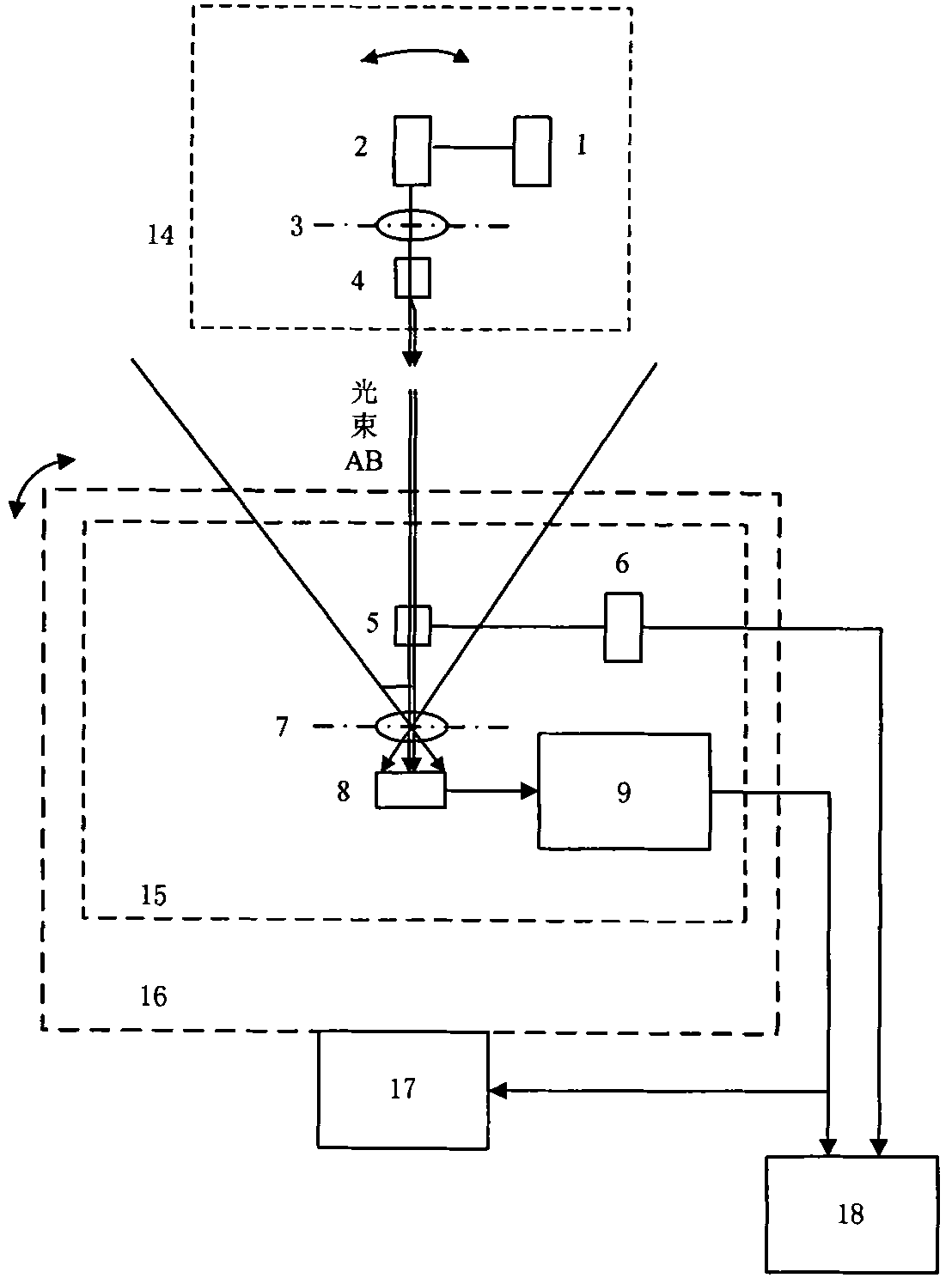
[0056] The device of the present invention comprises: beacon optical power supply 1, laser 2, collimating lens 3, lateral displacement polarization beam splitting prism 4, analyzer 5, rotating motor 6 with encoder, lens 7, PSD sensor 8, PSD Processing circuit 9 , azimuth angle display 10 , pitch angle display 11 , polarization base vector angle display 12 , receiving system power supply 13 , two-dimensional tracking turntable 16 , turntable controller 17 , and host computer 18 . Among them, parts 1-4 constitute the beacon light beam transmitting unit 14 ; 5-13, 16-18 constitute the beacon light beam receiving unit 15 .

[0057] Implementation steps: Beacon light power supply 1 and receiving system power supply 13 are both DC regulated power supplies that can ensure stable operation of the system. The laser, rotating motor, PSD processing circuit, and two-dimensional tracking turntable are powered, and the ripple of each power supply is less than 100mV, 50mV, and 10mV. Laser 2...


PUM


Abstract

The invention discloses a light beam position and polarization angle common light path detection device and method based on a photoelectric position sensor. The method comprises the following steps: utilizing a lateral excursion and polarization dispersion prism to shape an incident light beam, outputting orthogonal parallel polarized lights with proportionable light intensities and realizing the contactless space position attitude transfer function; enabling a receiving system to utilize a rotary motor with a coder to drive an analyzer to detect the beacon light polarization through rotation at a constant angular velocity, utilizing the horizontal photoelectric effect of a PSD (Phase-sensitive Detector) to measure the light spot imaging position of beacon light and reversely pushing a beacon light beam position coordinate according to the imaging principle; utilizing light current generated by gathering incident light intensities on the surface of the PSD to detect the incident light intensities, comparing with an angle instantaneously fed back by the rotary motor, obtaining the synchronous polarization angle information of a beacon light beam after the phase sensitive detection, and achieving the function of simultaneously adjusting and detecting the beacon light track and the base vector angle on a same light path and a device. The light beam position and polarization angle common light path detection device has the benefits of simple structure and simple components and is suitable for the multi-dimensional angle measurement demands.

Description

technical field [0001] The invention relates to beam orientation and polarization angle detection technology, in particular to a common optical path detection device and detection method using a photoelectric position sensor to detect beam orientation and polarization angle, which is applied in quantum communication, laser communication, target tracking or angle dynamic measurement . Background technique [0002] Abroad, in 1945, A.Rothen first designed an ellipsometer to measure the optical properties of the film surface. Since then, various measuring instruments based on polarized light measurement technology have emerged and matured, forming the branch of ellipsometry. The polarizer-system under test-compensator-analyzer (PSCA) structure has become a common structure in ellipsometer design. In 1969, Cahan, Spanier, etc. studied the rotating analyzer ellipsometer (RAE), which allowed the analyzer A to rotate around the optical axis at a constant angular velocity, and mea...

Claims


Application Information

Patent Timeline
IPC IPC(8): G01B11/26
Inventor 杨海马王建宇胡以华贾建军刘瑾强佳张亮吴金才
Owner SHANGHAI INST OF TECHNICAL PHYSICS - CHINESE ACAD OF SCI
Why Eureka
Try Eureka