Signal processing circuit of linear Hall sensor

A signal processing circuit, linear Hall technology, applied in the direction of using electric/magnetic devices to transmit sensing components, etc., can solve the problems of linearity deterioration, large layout area, complex design, etc., and achieve strong noise suppression and high linearity Effect

Active Publication Date: 2011-06-29
SHANGHAI HUAHONG GRACE SEMICON MFG CORP
View PDF0 Cites 22 Cited by
  • Summary
  • Abstract
  • Description
  • Claims
  • Application Information

AI Technical Summary

Problems solved by technology

[0004] In existing inventions, conventional designs usually use discrete oversampling ADCs, or second-order or even higher-order oversampling ADCs. These structures are not only complex in design but also re

Method used


Image

  • Signal processing circuit of linear Hall sensor
  • Signal processing circuit of linear Hall sensor
  • Signal processing circuit of linear Hall sensor

Examples


Embodiment Construction

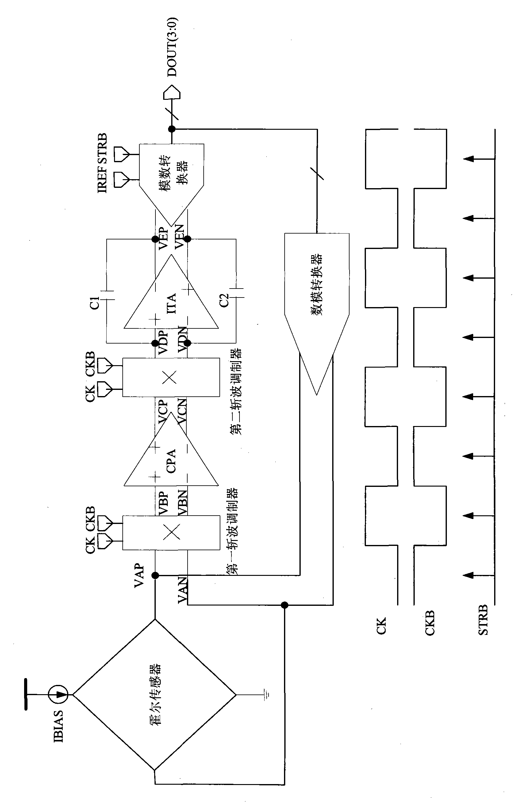
[0021] The invention discloses a signal processing circuit of a linear Hall sensor, such as figure 1 shown, including:

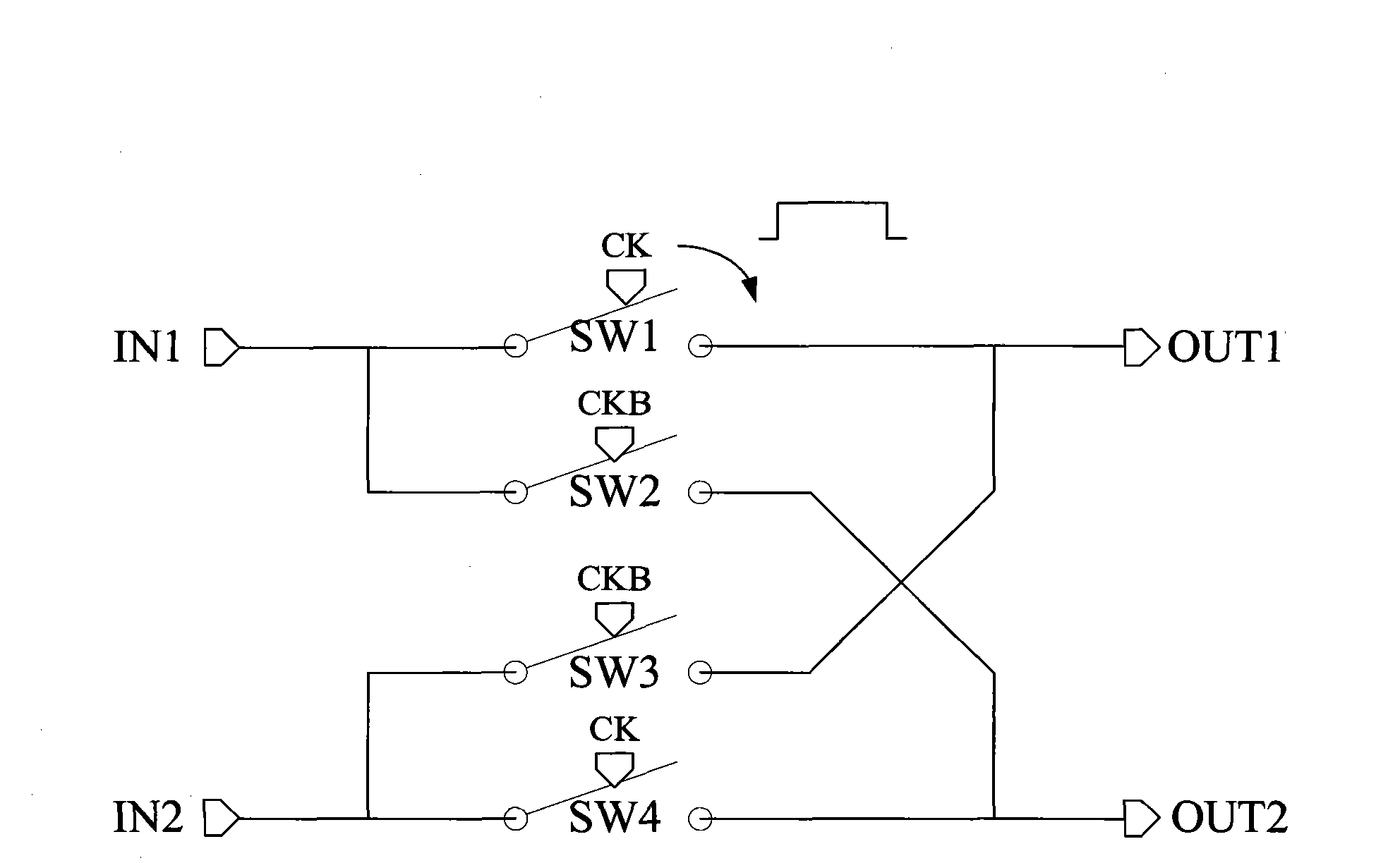
[0022] The first chopping modulator, the input terminal of the first chopping modulator is connected to the two voltage signal output terminals of the Hall sensor, and the two input signals are switched between positive phase and negative phase according to the frequency of the clock signal (CK, CKB). switch between phases, and output the switched voltage signal from the two signal output terminals of the first chopper modulator;

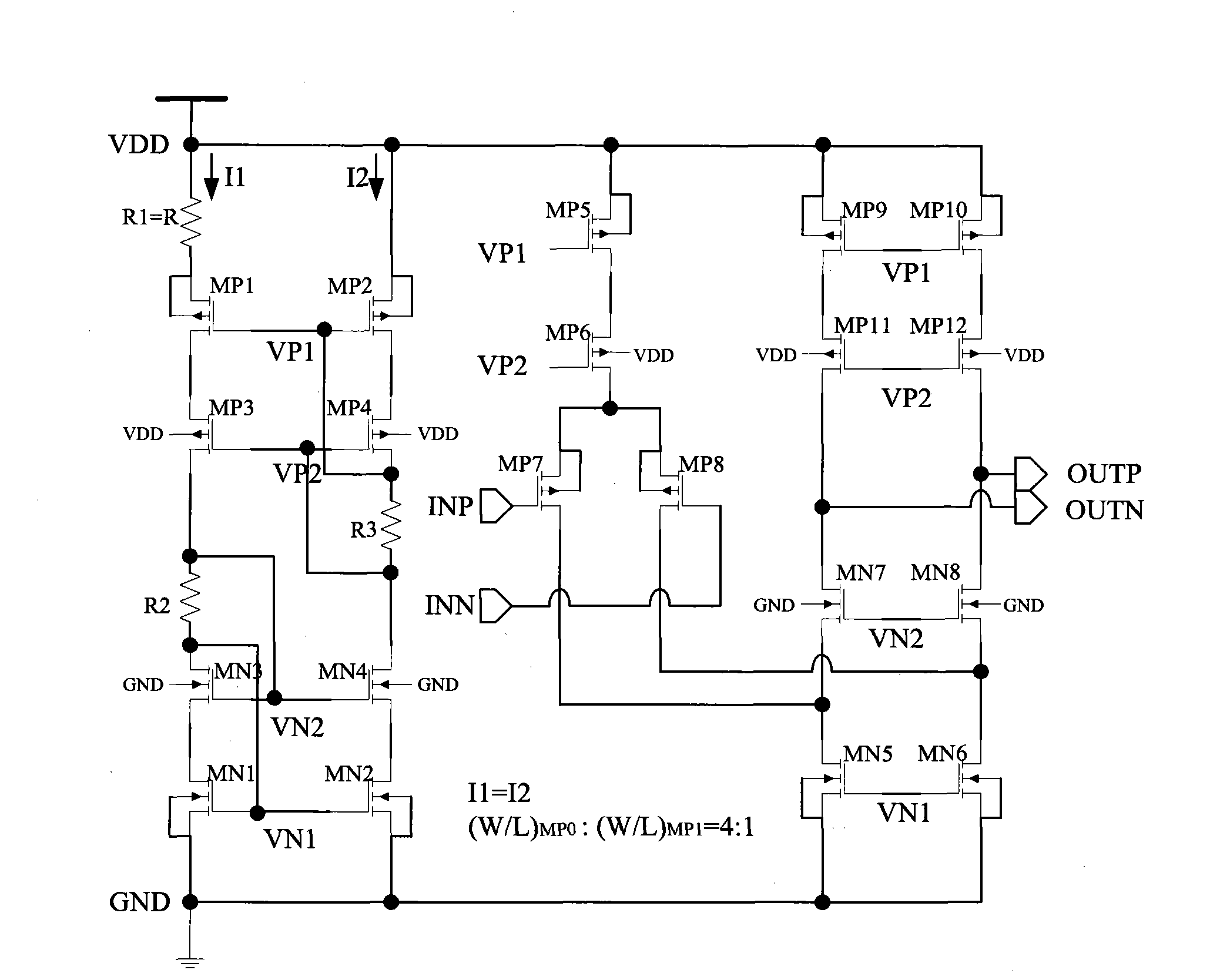
[0023] A chopping amplifier (CPA), the two input terminals of the chopping amplifier are connected to the two output terminals of the first chopping modulator, and the two voltage signals output by the first chopping modulator are converted into two currents signal, and is output by the two output terminals of the chopper amplifier;

[0024] The second chopper modulator, the input terminal of the second chopper modulator is conn...


PUM


Abstract

The invention discloses a signal processing circuit of a linear Hall sensor, which comprises an over-sampling loop and two chopping modulators. The over-sampling loop consists of a CPA (chopping amplifier), a first order loop wave filter, a four-bit digital converter and a feedback circuit, wherein the first order loop filter contains a filter capacitor and an integrating amplifier (ITA). The two chopping modulators are respectively embedded in front of and behind the CPA. The CPA is an operational transconductance amplifier which linearly converts an outputted voltage signal into current and keeps fixed gain under the full conditions. The filter capacitor and the ITA are connected with an active first order wave filter of the over-sampling loop. The four-bit digital converter converts a filtered signal into a four-bit digital signal; and the feedback formed by a four-bit DAC (Digital-to-Analog Converter) and a Hall dish converts an output code into feedback voltage; and the feedback voltage is subtracted from an inputted signal. As the inputted signal is very weak, the offset voltage of the CPA and the flicker noise are modulated by the chopping modulators in front of and behind the CPA into a high-frequency band and are filtered by a wave filter. The constant Gm in the CPA keeps the loop more stable under the full conditions.

Description

technical field [0001] The invention relates to a signal processing circuit, in particular to a signal processing circuit of a linear Hall sensor. Background technique [0002] The linear Hall sensor senses the magnetic field and converts the change of the magnetic flux passing through the sensor into an electrical signal. In the past, people usually directly amplify the Hall induced electromotive force through an amplifier to control other systems. At present, in the face of lower cost and higher efficiency requirements, Hall disks are directly embedded in CMOS technology and SOC systems (system on chip systems on chips) are used. Hall effect devices in CMOS technology are capable of sensing magnetic fields, but with very low sensitivity. For the requirement of high linearity, it is not suitable to directly amplify the Hall induced electromotive force. Built-in oversampling ADC is a common design at present. [0003] In the control system, the Hall sensor is required to ...

Claims


Application Information

Patent Timeline
IPC IPC(8): G01D5/14
Inventor 王楠周平古炯钧张宁骆川
Owner SHANGHAI HUAHONG GRACE SEMICON MFG CORP
Why Eureka
Try Eureka