Anti-hopping vacuum contactor of high-speed frame-type repulsion mechanism

A technology of vacuum contactor and repulsion mechanism, applied in high-voltage air circuit breakers, high-voltage/high-current switches, electrical components, etc., can solve problems such as long contact time, scattering, and coil damage, and achieve reliable operation, energy saving, The effect of simple structure

Inactive Publication Date: 2011-06-29
DALIAN UNIV OF TECH
View PDF5 Cites 19 Cited by
  • Summary
  • Abstract
  • Description
  • Claims
  • Application Information

AI Technical Summary

Problems solved by technology

The traditional vacuum contactor uses an electromagnetic mechanism to drive the action of the vacuum interrupter. Due to the inductance effect of the electromagnetic coil, the contact time is long, so it cannot meet the requirements in some specific occasions.
In addition, the maintenance of the electromagnetic coil needs to be charged all the time, which consumes more energy.
The high-speed repulsion mechanism has been studied more in recent years, and there are mainly the following problems that plague its practical application: 1. The collision and rebound of the high-speed repulsion mechanism is difficult to solve in a short stroke; 2. The placement of the repulsion coil has not been very good. Therefore, the present invention intends to adopt a frame-type repulsion mechanism, and place the coil disk in the frame disk made of pure iron, and calculate and analyze the best Electromagnetic field effect, thus effectively protecting the working strength of the coil

Method used


Image

  • Anti-hopping vacuum contactor of high-speed frame-type repulsion mechanism
  • Anti-hopping vacuum contactor of high-speed frame-type repulsion mechanism
  • Anti-hopping vacuum contactor of high-speed frame-type repulsion mechanism

Examples


Embodiment Construction

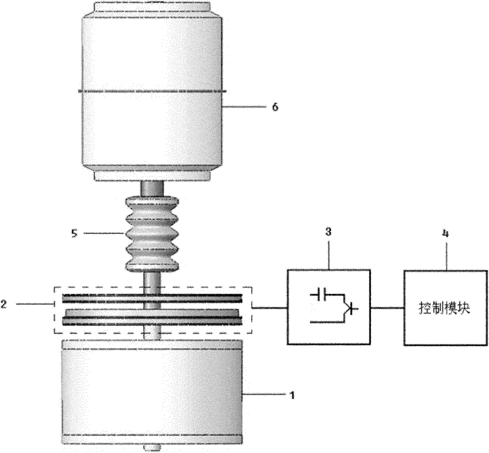
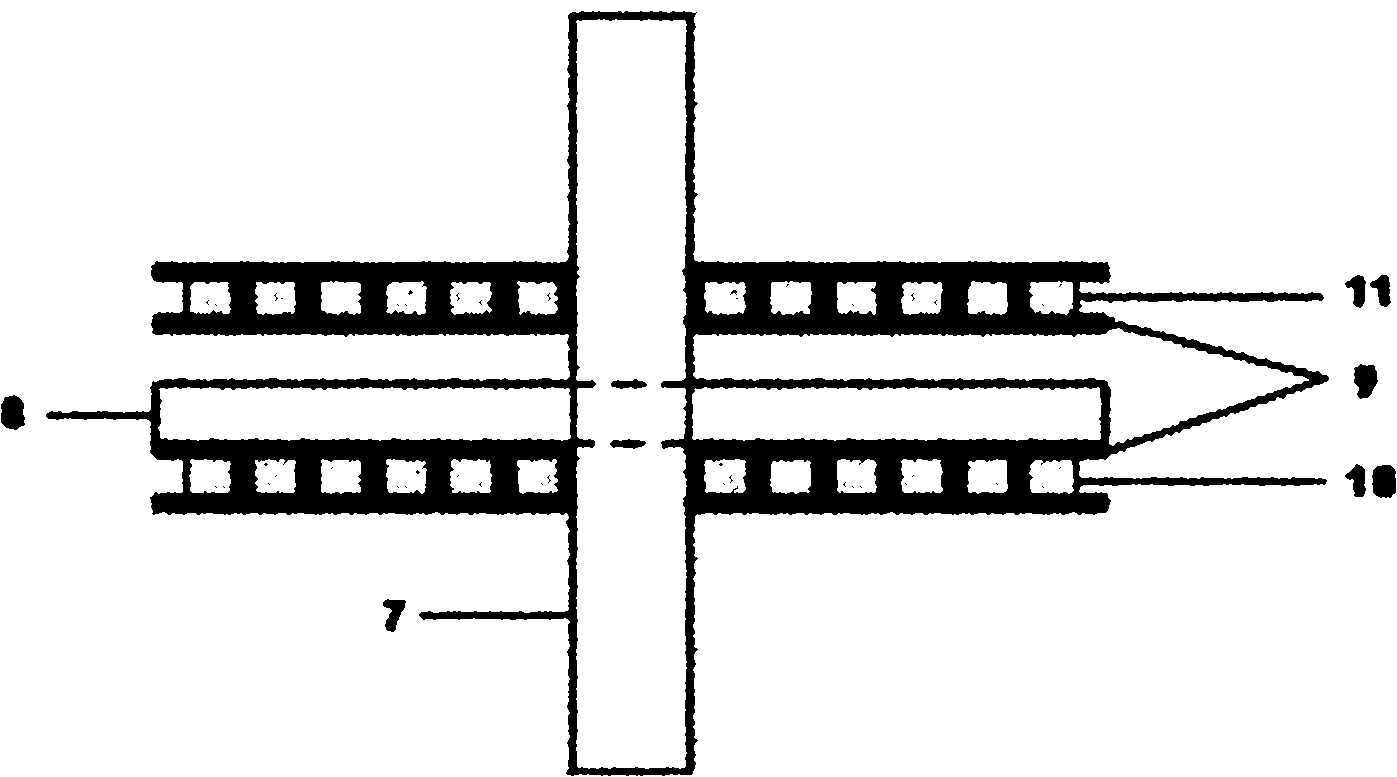
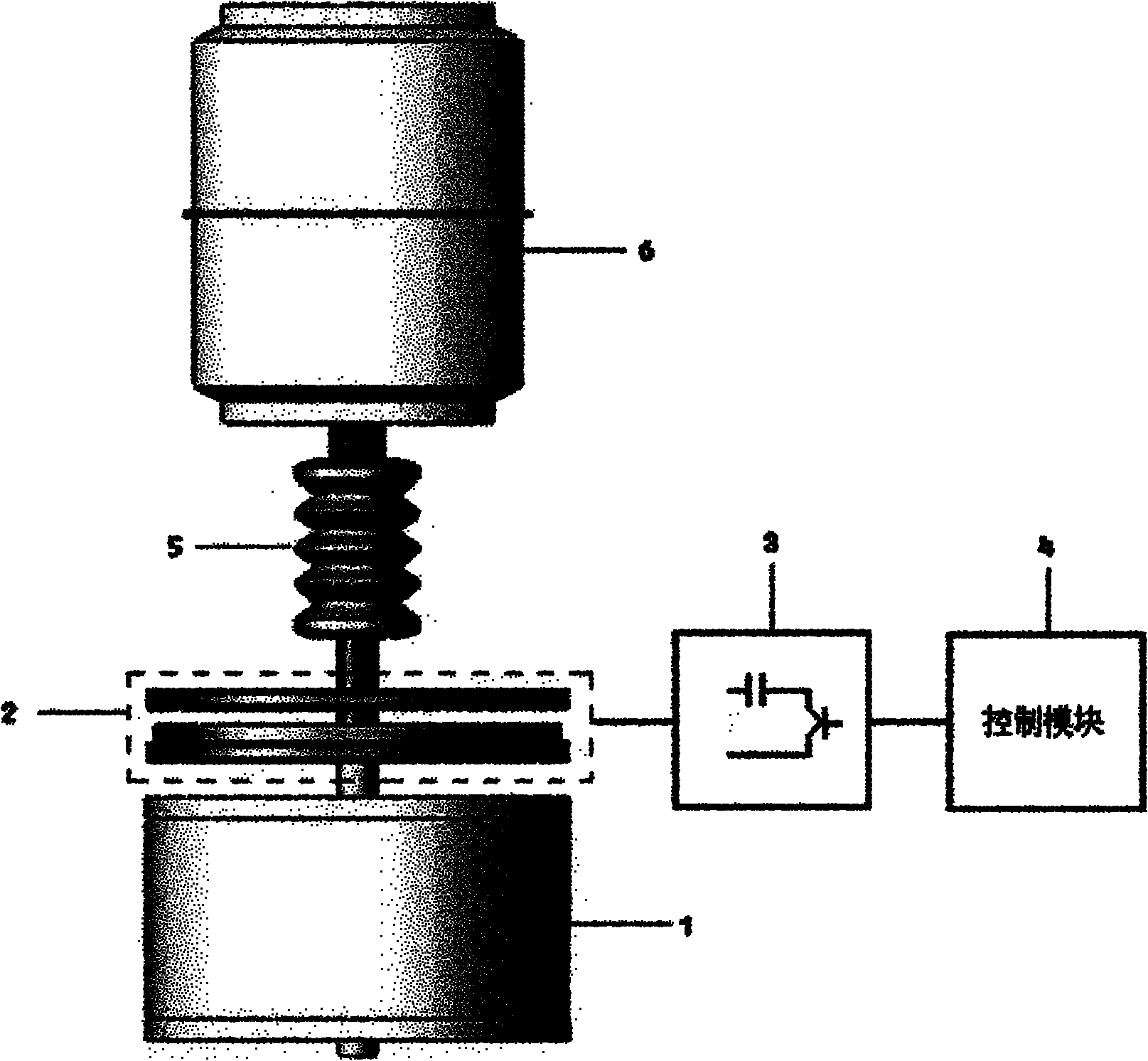
[0012] of the present invention figure 2 The middle frame type high-speed repulsion mechanism is typically used for figure 1 The frame type repulsion mechanism in. according to figure 1 The schematic diagram of the functional structure and figure 2 As shown in the internal structure diagram of the frame-type high-speed repulsion mechanism, 1 permanent magnet mechanism is connected with 2 frame-type repulsion mechanism, 2 is connected with 5 insulating pull rods, 5 is connected with 6 vacuum interrupter. 2. The 11 opening coils and 10 closing coils in the frame-type repulsion mechanism are respectively connected to the 3 capacitor pulse discharge device, and the 3 capacitor pulse discharge device is connected to the 4 control module. When the contactor needs to be closed, the 4 control module sends a command to make the 3 capacitor pulse discharge device discharge the 10 closing coils in the 2 frame repulsion mechanism, and the 8 copper discs in the 2 frame repulsion mecha...


PUM


Abstract

The invention discloses an anti-hopping vacuum contactor of a high-speed frame-type repulsion mechanism, which belongs to the technical fields of electric engineering and machinery. In the invention, the high-speed frame-type repulsion mechanism is matched with a permanent magnet mechanism to manufacture an operation part of a high-speed contactor, and the operation part is used for driving a vacuum arc extinguish chamber to form a high-speed vacuum contactor. By the high-speed frame-type repulsion mechanism used by the contactor, an opening coil and a closing coil are arranged in a pure iron frame to ensure that the coils cannot be damaged in the high-speed movement process. Due to the adoption of the permanent magnet mechanism, the position of the vacuum contactor can be kept, and electric energy can be saved. In the repulsion mechanism, electric discharge stimulation to the closing coil is used at the final stage of the opening operation, so that collision hopping caused by a high-speed opening action in short stroke can be effectively prevented. In the invention, a high-efficient, reliable and energy-saving contactor device is provided for a switch used in occasions in which high-speed operation is required, such as a power transmission occasion, a system protection occasion and the like, and the vacuum contactor has a simple structure and is easy to maintain.

Description

technical field [0001] The invention belongs to the field of electrical engineering and mechanical technology, and relates to a switch device for high-speed switching of electric power and electric energy conversion in an electric power system. Background technique [0002] With the gradual improvement of users' requirements for power quality, users have higher and higher requirements for the action speed of switches in many occasions, such as the switching of faulty power supplies for primary loads; the instantaneous introduction of transfer currents in DC circuit breakers; when the voltage drops Transient compensation and so on all require high-speed and reliable operation of mechanical switches. The traditional vacuum contactor uses an electromagnetic mechanism to drive the action of the vacuum interrupter. Due to the inductance effect of the electromagnetic coil, the contact time is long, so it cannot meet the requirements in some specific occasions. In addition, the ma...

Claims


Application Information

Patent Timeline
Patent Type & Authority Applications(China)
IPC IPC(8): H01H33/66H01H33/666
Inventor 董恩源郑占锋田鹏邹啟涛
Owner DALIAN UNIV OF TECH
Why Eureka
Try Eureka