Dehumidifier

A technology for dehumidifiers and cabinets, which can be used in household heating, lighting and heating equipment, and prevention of condensed water, etc. It can solve the problems of increasing the cost of dehumidifier production materials, high overall cost of dehumidifiers, and vibrations, so as to save production costs , low noise and reduced vibration

Inactive Publication Date: 2011-07-06
LG ELECTRONICS (TIANJIN) APPLIANCES CO LTD
View PDF6 Cites 4 Cited by
  • Summary
  • Abstract
  • Description
  • Claims
  • Application Information

AI Technical Summary

Problems solved by technology

[0009] In the prior art dehumidifiers, the chassis and the water tank are two separate parts. In order to ensure the support strength of the chassis to the dehumidifier as a whole, the chassis is made of metal, and the chassis of sheet metal parts increases the production material cost of the dehumidifier. However, two sets of different molds are required to produce the chassis and water tank, so two sets of molds are required, resulting in a higher overall product cost of the dehumidifier
In addition, the compressor in the prior art is directly fixed on the chassis by screws, which is easy to vibrate and generate noise during work.

Method used


Image

  • Dehumidifier
  • Dehumidifier
  • Dehumidifier

Examples


Embodiment Construction

[0028] The present invention is described in detail below with reference to accompanying drawing and embodiment:

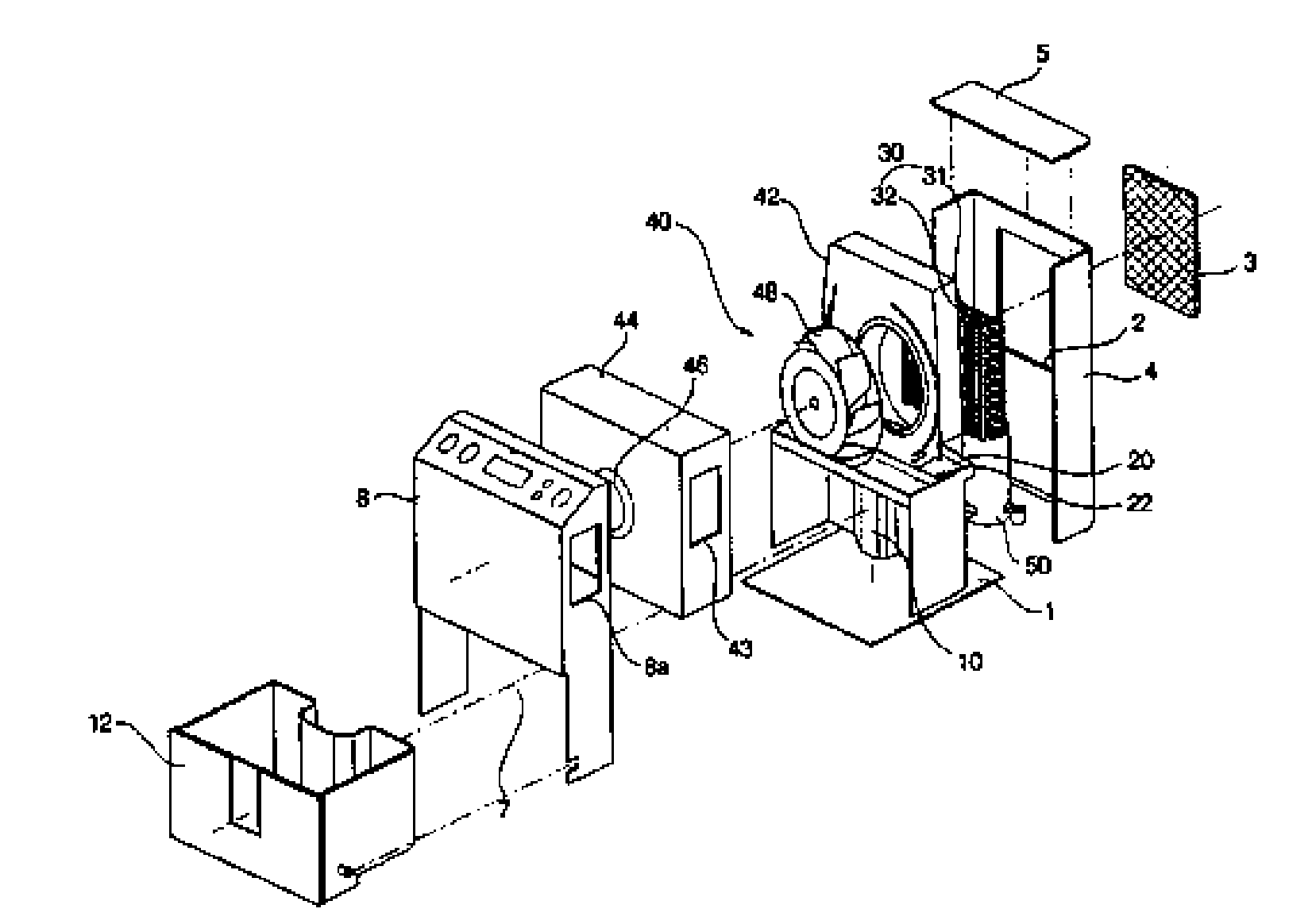
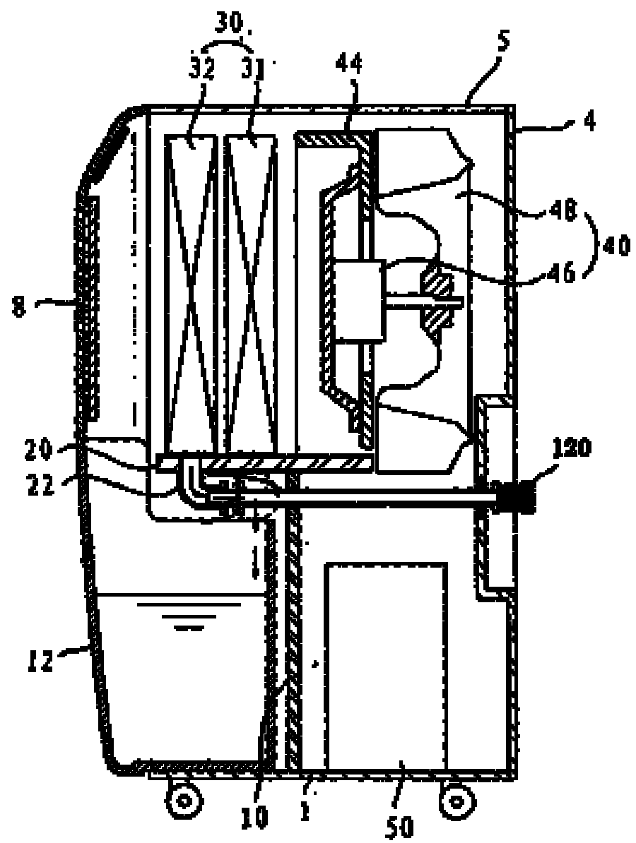
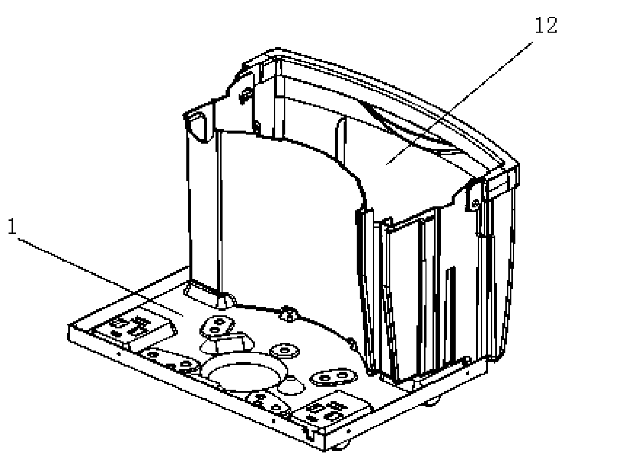
[0029] Figure 4 It is a schematic diagram of the decomposition structure of the dehumidifier of the present invention; Figure 5 It is a structural schematic diagram of the chassis and water tank in the dehumidifier of the present invention; Image 6 It is a schematic diagram of the chassis and water tank in the dehumidifier of the present invention from another perspective.

[0030] Such as Figure 4 to Figure 6 As shown, in the dehumidifier of the present invention, the cabinet 4 forms the appearance of the dehumidifier, accommodates and protects the various components of the dehumidifier; Therefore, the evaporator is in a low temperature state. When the inhaled humid air passes through the evaporator, the moisture in the air condenses on the evaporator into condensed water, and the condensed water falls into the water tray after being collected; the condens...


PUM


Abstract

The invention provides a dehumidifier. The dehumidifier comprises a case, an evaporator, a condenser, a water-containing plate, a fan, a water tank, a compressor and a chassis; the water tank and the chassis have an integrated structure; the side wall of the water tank is formed by upward stretching the chassis; and the compressor, a water drainage part and a power line box are arranged on both sides of the water tank. The integrated structure of the chassis and the water tank can simplify the production and installation steps, and only one die is needed during production, so the manufacturing cost of the die is saved, and different parts can be produced without a plurality of dies; moreover, as the chassis and the water tank in the dehumidifier are uniformly made of the same engineering plastic, the production cost of the dehumidifier is reduced.

Description

technical field [0001] The invention belongs to the technical field of dehumidifiers, and specifically relates to a chassis and a water tank that are integrally formed, and components such as a compressor are arranged on both sides of the water tank, thereby reducing production costs while improving the utilization rate of the internal space of the product, and making the structural distribution of the components more precise. For a reasonable dehumidifier. Background technique [0002] Generally speaking, the dehumidifier introduces the humid air in the room into the inside of the chassis, reduces the humidity through a heat exchanger composed of an evaporator and a condenser with refrigerant flow, and then discharges the dehumidified air into the room to reduce the humidity. Device for indoor humidity purposes. [0003] figure 1 It is a schematic diagram of the decomposition structure of the prior art dehumidifier; figure 2 is a side sectional view of a prior art dehum...

Claims


Application Information

Patent Timeline
IPC IPC(8): F24F1/02F24F13/22
Inventor 鲍长桥杨佩元
Owner LG ELECTRONICS (TIANJIN) APPLIANCES CO LTD
Why Eureka
Try Eureka