Tri-differential confocal microscope imaging method with high axial resolution and imaging device

A differential confocal, high-resolution technology, applied in microscopes, optics, instruments, etc., can solve the problems of high environmental requirements, difficulty in ensuring the stability of pinhole displacement, and low utilization of light energy. The effect of low environmental requirements, improved axial resolution, and simple structure

Active Publication Date: 2012-10-10
INST OF OPTICS & ELECTRONICS - CHINESE ACAD OF SCI
View PDF2 Cites 0 Cited by
  • Summary
  • Abstract
  • Description
  • Claims
  • Application Information

AI Technical Summary

Problems solved by technology

However, this method has a low light energy utilization rate in weak light measurement, and because the method uses a non-common optical path structure, it is difficult to ensure the stability of the pinhole displacement, and the use environment requires high requirements.

Method used


Image

  • Tri-differential confocal microscope imaging method with high axial resolution and imaging device
  • Tri-differential confocal microscope imaging method with high axial resolution and imaging device
  • Tri-differential confocal microscope imaging method with high axial resolution and imaging device

Examples


Embodiment approach

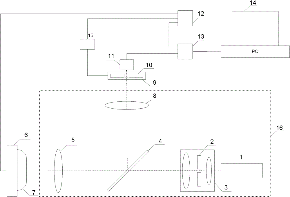
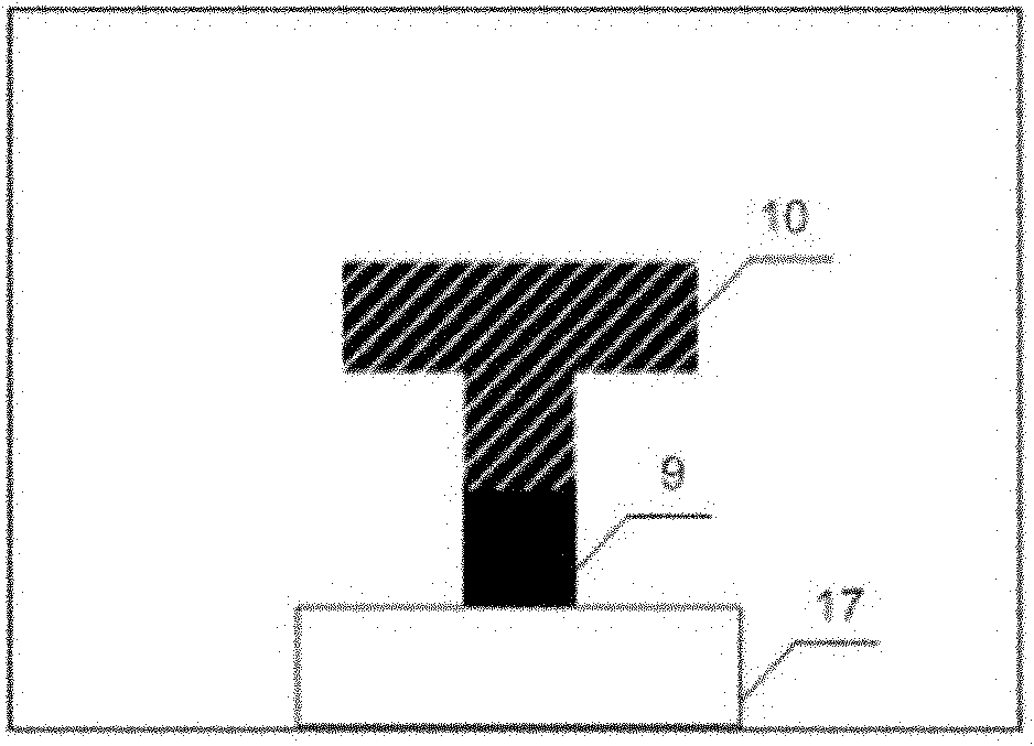
[0027] The specific embodiment of the present invention is as follows: the pinhole 10 at the optical detection place is bonded to one end of the pinhole axial micro-displacement device 9 with an adhesive. In this embodiment, the pinhole axial micro-displacement device 9 adopts a piezoelectric ceramic scanner. The other end of the pinhole axial micro-displacement device 9 is bonded on the substrate 17 . The axial movement of the pinhole 10 at the optical detection point is controlled by the pinhole axial micro-displacement device 9 . First, the signal synchronization device 12 sends a control signal. The signal synchronization device in this embodiment is a synchronization circuit board, which controls the pinhole axial micro-displacement driving device 15 to generate a driving signal. In this embodiment, the pinhole axial micro-displacement driving device 15 is a high-voltage amplifier, which generates a driving voltage signal to drive the pinhole axial micro-displacement devi...


PUM


Abstract

The invention provides a tri-differential confocal microscope imaging method with high axial resolution and an imaging device. The axial resolution of the original confocal microscope is improved by tri-differential detection. In the optical path of a system, the axial position of a pinhole at the optical detecting position of the confocal microscope can be changed by a pinhole axial micro-displacement device, thus realizing tri-differential detection of signals. The imaging method and the imaging device have the advantages of ensuring the stability of the displacement of the pinhole and simultaneously improving the resolving power, and being simple to realize.

Description

technical field [0001] The invention relates to a device and an imaging method for improving the resolution of a confocal microscope, in particular to a three-differential confocal microscope imaging method and an imaging device with high axial resolution, which realizes three-differential detection of signals to improve confocal microscopy. Axial-resolution imaging of focal microscopes. Background technique [0002] The confocal microscope was first proposed by the American scholar M.Minsky in 1957, and obtained the US patent in 1961, the patent number is US3013467. In a confocal microscope, the point light source, point object, and point detector are placed in corresponding conjugate positions, and the resolution of the system is significantly improved. The basic principles of confocal microscopy are as follows: image 3 As shown, the light emitted by the point light source 20 passes through the objective lens 21 and the half-mirror 22, and then irradiates a point on the ...

Claims


Application Information

Patent Timeline
Patent Type & Authority Patents(China)
IPC IPC(8): G02B21/36G02B21/00
Inventor 张雨东李昊卢婧史国华
Owner INST OF OPTICS & ELECTRONICS - CHINESE ACAD OF SCI
Why Eureka
Try Eureka