Method for fixing focus and measuring curvature radius by confocal interference
A technology of interferometric measurement and radius of curvature, which is applied in the direction of measuring devices, optical instrument testing, and testing optical performance, etc., can solve the problems of increasing measurement random errors, low degree of automation, and optical path adjustment system errors, etc., to improve measurement accuracy , Improve the focus sensitivity, improve the effect of focus accuracy
- Summary
- Abstract
- Description
- Claims
- Application Information
AI Technical Summary
Problems solved by technology
Method used
Image
Examples
Embodiment 1
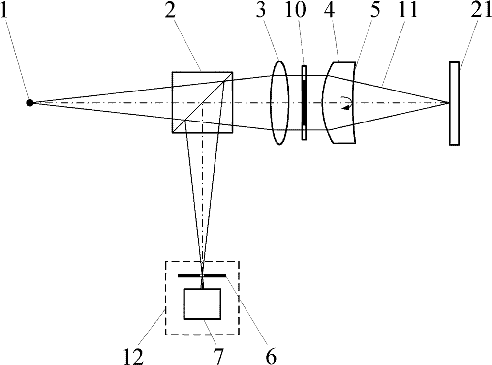
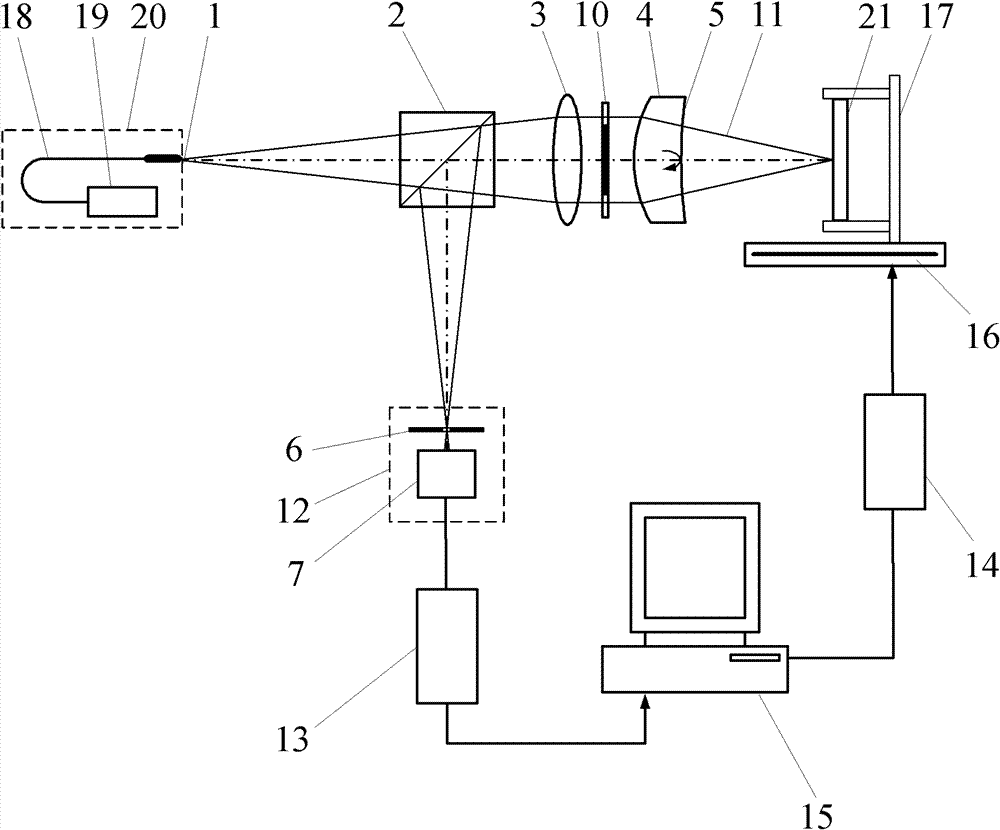
[0057] When using this method to locate the focal point of the measuring beam, as attached image 3 Shown, the confocal interference fixed focus device, the measurement steps are:
[0058] (a) Start the measurement software in the main control computer 15, turn on the laser 19, and the light emitted by the laser 19 is transmitted through the optical fiber 18 to form a point light source 1. The light emitted by the point light source 1 forms a measuring beam 11 after passing through the beam splitter 2, the collimator lens 3 and the limmet lens 4;
[0059] (b) Adjust the lume lens 4 so that it has the same optical axis as the collimating lens 3 . The collimating lens 3 collimates the light generated by the point light source 1 into parallel light. Parallel light is irradiated on the Qiming lens 4, part of the light is reflected on the Qiming lens reference surface 5 and returns along the original optical path, and the returning light passes through the collimating lens 3 and ...
Embodiment 2
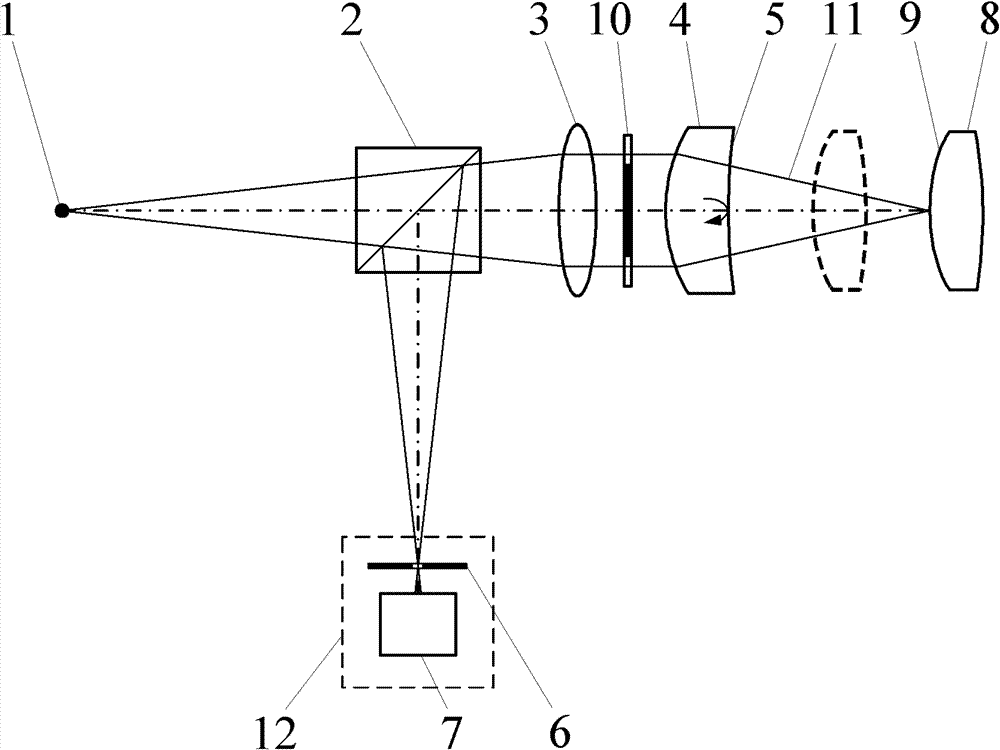
[0064] Use this fixed-focus method to measure the curvature radius of a convex spherical surface, as shown in the attached Figure 4 Shown, the confocal interference radius of curvature measurement device, the measurement steps are:
[0065] (a) Start the measurement software in the main control computer 15, turn on the laser 19, and the light emitted by the laser 19 is transmitted through the optical fiber 18 to form a point light source 1. The light emitted by the point light source 1 forms a measuring beam 11 after passing through the beam splitter 2, the collimator lens 3 and the limmet lens 4;
[0066] (b) Adjust the lume lens 4 so that it has the same optical axis as the collimating lens 3 . The collimating lens 3 collimates the light generated by the point light source 1 into parallel light. Parallel light is irradiated on the Qiming lens 4, part of the light is reflected on the Qiming lens reference surface 5 and returns along the original optical path, and the retur...
PUM
 Abstract
Description
Claims
Application Information
 - R&D
- Intellectual Property
- Life Sciences
- Materials
- Tech Scout
- Unparalleled Data Quality
- Higher Quality Content
- 60% Fewer Hallucinations
Browse by: Latest US Patents, China's latest patents, Technical Efficacy Thesaurus, Application Domain, Technology Topic, Popular Technical Reports.
© 2025 PatSnap. All rights reserved.Legal|Privacy policy|Modern Slavery Act Transparency Statement|Sitemap|About US| Contact US: help@patsnap.com


