Laser stimulated emission loss three-dimensional super-resolution split-pupil differential confocal imaging method and device

A laser stimulated emission, differential confocal technology, applied in the direction of using optical devices, measuring devices, instruments, etc., can solve problems such as limited applications

Active Publication Date: 2017-07-11
BEIJING INSTITUTE OF TECHNOLOGYGY
View PDF1 Cites 0 Cited by
  • Summary
  • Abstract
  • Description
  • Claims
  • Application Information

AI Technical Summary

Problems solved by technology

Unfortunately, although the patents "Differential Confocal Scanning Detection Method with High Spatial Resolution" and "Super-resolution Laser Polarization Differential Confocal Imaging Method and Device" make the axial resolution reach the nanometer level, their lateral resolution The force can only break through about 30% of the classical diffraction lateral resolution, which limits its application in fields requiring high lateral resolution

Method used


Image

  • Laser stimulated emission loss three-dimensional super-resolution split-pupil differential confocal imaging method and device
  • Laser stimulated emission loss three-dimensional super-resolution split-pupil differential confocal imaging method and device
  • Laser stimulated emission loss three-dimensional super-resolution split-pupil differential confocal imaging method and device

Examples


Embodiment 1

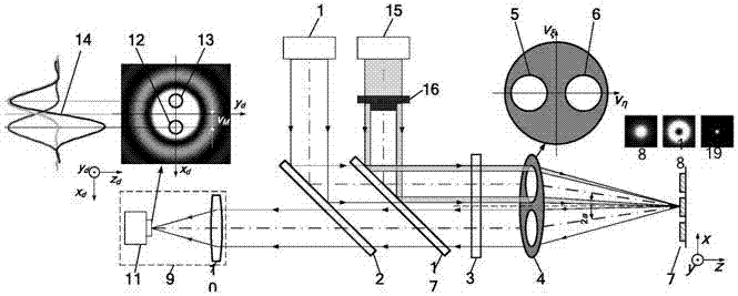
[0047] Such as figure 1 As shown, the laser stimulated emission loss microscopic three-dimensional super-resolution split pupil differential confocal imaging method, the test steps are as follows:

[0048] First, the wavelength emitted from the excitation laser system 1 is λ 1 After being reflected by the first dichroic mirror 2, the parallel light beam passes through the second dichroic mirror 17, the quarter wave plate 3 and the illumination pupil 5, and is focused on the surface of the measured sample 7 by the measuring objective lens 4, and the measured sample 7 reflects The light with sample information (or excited fluorescence) passes through the collection pupil 6 of the measurement objective 4, the quarter wave plate 3, the second dichroic mirror 17 and the first dichroic mirror 2, and enters the split pupil differential common Focus detection system 9; Confocal lens 10 and image acquisition system 11 are placed successively in the sub-pupil differential confocal dete...

Embodiment 2

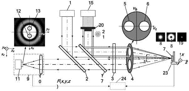
[0054] Such as figure 2 As shown, replacing the beam shaping system 16 in Embodiment 1 with the annular beam shaping system 20 can constitute a stimulated emission loss split pupil three-dimensional super-resolution differential confocal imaging method and device using the annular beam shaping system, and the annular beam shaping system The system 20 can be an annular pupil filter, a binary optical diffraction device with an annular phase distribution, etc., and shapes the quenched laser beam into an annular beam 21 .

[0055] figure 2 Among them, the illumination pupil can be a circular pupil, a D-shaped pupil or a pupil of other shapes; it can also be a ring pupil, which directly replaces the ring beam shaping system and shapes the incident beam into a ring beam.

[0056] All the other measuring methods are the same as in Example 1.

Embodiment 3

[0058] Such as image 3 As shown, a schematic diagram of an embodiment of a laser stimulated emission loss three-dimensional super-resolution split-pupil differential confocal imaging device, the principle of which is:

[0059] First, the sample 7 to be tested is placed on the scanning table 23. The scanning table 23 adopts a macro-micro combination method, and a micro-displacement two-dimensional table based on a piezoelectric ceramic driver PZT and a capacitive sensor is integrated on the x-y macro table. , start the measurement software in the main control computer 24.

[0060] The parallel light beam emitted by the excitation laser system 1 is reflected by the first dichroic mirror 2, passes through the second dichroic mirror 17, the quarter-wave plate 3 and the illumination pupil 5, and is focused on the measured sample 7 by the measuring objective lens 4. The light with sample information (or excited fluorescence) reflected by the sample 7 passes through the collection ...


PUM


Abstract

The invention belongs to the technical field of optical precision imaging testing, and relates to a laser stimulated emission loss three-dimensional super-resolution split-pupil differential confocal imaging method and device. The core idea of ​​the present invention is to organically integrate the split-pupil laser differential confocal detection technology and the laser stimulated emission loss imaging technology, and integrate the high-resolution and high-scattering suppression characteristics of the split-pupil differential confocal detection technology. The confocal technology improves the axial resolution, and the stimulated emission depletion microscopy improves the lateral resolution, which in turn improves the spatial resolution and anti-sample scattering ability of the system. The device includes an excitation laser system, a first dichroic mirror, a quarter wave plate, a measuring objective lens, a sample, a scanning table, a quenching laser system, a beam shaping system, a second dichroic mirror, and a split-pupil differential confocal detection system and data processing module. The invention has three-dimensional super-resolution imaging and detection capabilities of high spatial resolution and high scattering sample suppression, and has broad application prospects in the field of micro-nano technology.

Description

technical field [0001] The invention belongs to the technical field of optical precision imaging testing, and relates to a laser stimulated emission loss three-dimensional super-resolution split-pupil differential confocal imaging method and device, which can be used for three-dimensional super-resolution imaging and detection of nanometer-level geometric parameters in the field of micro-nano technology. [0002] technical background [0003] Confocal microscopy is unique in the field of high-resolution optical microscopic detection due to its unique longitudinal tomographic imaging capabilities and the advantages of being easy to combine with super-resolution technology, and plays an extremely important role in nanoscale imaging and detection . [0004] At present, in the study of improving the resolution of confocal microscopy imaging, differential confocal microscopy, biaxial confocal microscopy, confocal interference microscopy, 4π confocal microscopy and stimulated emiss...

Claims


Application Information

Patent Timeline
Patent Type & Authority Patents(China)
IPC IPC(8): G01B11/24G01B11/00
Inventor 赵维谦邱丽荣王允
Owner BEIJING INSTITUTE OF TECHNOLOGYGY
Why Eureka
Try Eureka