
Solar battery assembly and preparation method thereof

A technology for solar cells and modules, applied in electrical components, semiconductor/solid-state device manufacturing, circuits, etc., can solve problems such as potential safety hazards, inability to flexibly obtain voltage and current values, and inability to apply battery modules to inverters, to ensure safety effect

Active Publication Date: 2011-07-06
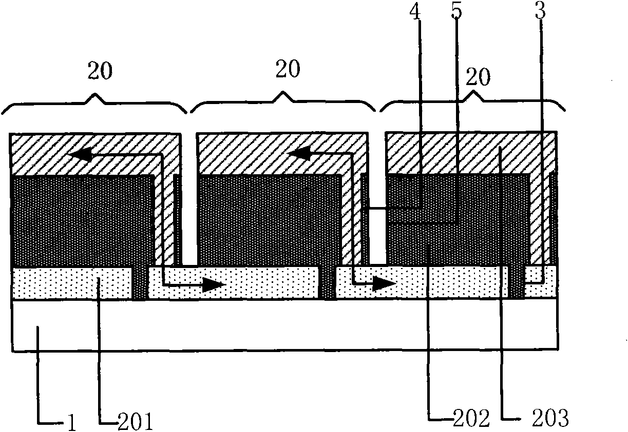
BOE TECH GRP CO LTD +1
View PDF0 Cites 47 Cited by
  • Summary
  • Abstract
  • Description
  • Claims
  • Application Information

AI Technical Summary

Problems solved by technology

[0006] However, the inventor found the following defects in the prior art during the research of the present invention: in order to find a balance between "dead area" and "resistance" when manufacturing solar cell components, the solar energy of the set area Cell modules typically form a fixed number of solar cells
Since a certain area of ​​solar cell components using the above-mentioned series connection method has fixed voltage and current values, it is impossible to flexibly obtain the desired voltage and current values; if the solar cell components with such a high voltage are exposed to the external environment, then Causes a great safety hazard; and the existing inverter cannot be applied to a larger area of ​​battery components with high voltage

Method used


Image

  • Solar battery assembly and preparation method thereof
  • Solar battery assembly and preparation method thereof
  • Solar battery assembly and preparation method thereof

Examples


Embodiment 1

[0031] This embodiment provides a solar cell module, Figure 4 Is a schematic diagram of the structure of the solar cell module provided in the first embodiment of the present invention, Figure 5 for Figure 4 The schematic circuit diagram of the solar cell module shown. From Figure 4 with Figure 5 It can be seen that the solar cell module includes a plurality of solar cells 20 formed on the transparent substrate 1, and each solar cell 20 includes a transparent conductive film 201, a solar cell layer 202, and a metal back electrode 203 stacked in sequence, adjacent to each other. The solar cells 20 are connected in series through the laser scribing process, that is, it can be realized by the first laser scribing 3, the second laser scribing 4, and the third laser scribing 5. Among them, it also includes: at least one fourth laser scribe line 6, which penetrates the metal back electrode 203, the solar cell layer 202 and the transparent conductive film 201, and disconnects adja...

Embodiment 2

[0039] This embodiment provides a method for manufacturing a solar cell module, Figure 7 This is a flow chart of the method for preparing a solar cell module provided in the second embodiment of the present invention. The method for preparing a solar cell module includes sequentially depositing a transparent conductive film material layer, a solar cell material layer and a metal back electrode material layer on a transparent substrate, And forming a plurality of solar cells connected in series through a laser scribing process 10, and further includes the following step 20:

[0040] Perform a fourth laser scribing on the formed solar cell module, cutting through the metal back electrode material layer, solar cell material layer and transparent conductive film material layer, and disconnecting adjacent solar cells to form at least two independent cells Unit, the battery unit is composed of solar cells connected in series.

[0041] The present invention divides the solar cell module...


PUM


Abstract

The invention relate to a solar battery assembly and a preparation method thereof. The solar battery assembly comprises a plurality of solar batteries and at least one fourth laser scribing, wherein each solar battery comprises a transparent conductive film, a solar battery layer and a metal back electrode which are sequentially overlapped, and the adjacent solar batteries are connected in serieswith each other through a laser scribing process; the fourth laser scribing penetrates through the metal back electrodes, the solar battery layers and the transparent conductive films, and the adjacent solar batteries are disconnected to form at least two independent battery units, wherein each battery unit comprises the solar batteries connected in series. The solar batteries assembly is dividedinto a plurality of independent battery units through the fourth laser scribing so that each battery unit comprises the specified number of solar batteries connected in series, therefore, the required working voltage and current can be obtained.

Description

Technical field [0001] The invention relates to a solar cell preparation technology, in particular to a solar cell component and a preparation method thereof. Background technique [0002] Solar cells have the characteristics of a wide range of raw materials, non-toxic, thin material thickness, low energy consumption in the production process and large-scale production, which can greatly reduce the cost of solar cells. [0003] At present, in order to achieve the optimal voltage and current of solar cells, an integration technology of connecting multiple solar cells in series to form solar cell modules is usually adopted. [0004] figure 1 It is a schematic diagram of the structure of a solar cell module in the prior art, figure 2 Yes figure 1 The schematic circuit diagram of the solar cell module shown. From figure 1 with figure 2 It can be seen that the solar cell module, through the first laser scribing 3, the second laser scribing 4, and the third laser scribing 5, connects a ...

Claims


Application Information

Patent Timeline
IPC IPC(8): H01L27/142H01L31/042H01L21/82H01L31/18H01L31/0463
CPCY02E10/50Y02P70/50
Inventor 李贵君韩晓艳宋行宾
Owner BOE TECH GRP CO LTD
Learn More