Millimeter-wave 360-DEG omnidirectional-scan dielectric cylinder lens antenna

A lens antenna, dielectric column technology, applied in the direction of antennas, antenna arrays, electrical components, etc., to achieve low cost, convenient connection, and simple effects

Inactive Publication Date: 2011-07-13
ZHEJIANG UNIV
View PDF1 Cites 36 Cited by
  • Summary
  • Abstract
  • Description
  • Claims
  • Application Information

AI Technical Summary

Problems solved by technology

[0009] However, domestic and international research on millimeter-wave multi-beam antennas is still limited to the realization of large-angle scanning, so for the realization of 3

Method used


Image

  • Millimeter-wave 360-DEG omnidirectional-scan dielectric cylinder lens antenna
  • Millimeter-wave 360-DEG omnidirectional-scan dielectric cylinder lens antenna
  • Millimeter-wave 360-DEG omnidirectional-scan dielectric cylinder lens antenna

Examples


Embodiment Construction

[0037] The present invention will be further described below in conjunction with the accompanying drawings and embodiments.

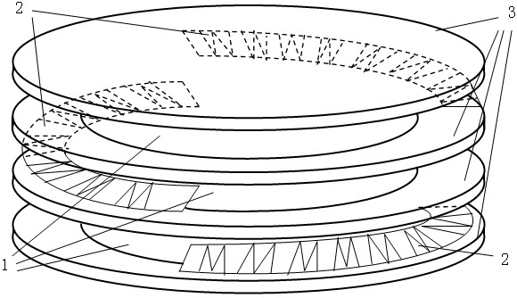
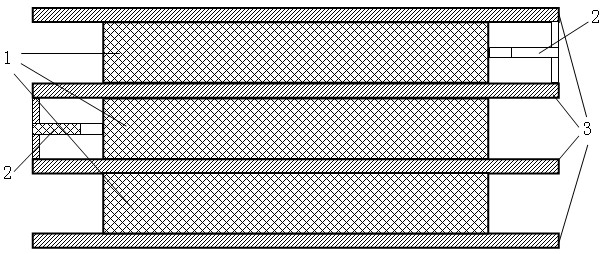
[0038] In the case of horizontal polarization, in order to ensure that the parallel plate waveguide composed of two adjacent metal discs excites TE 10 mode, the height of the parallel-plate waveguide must be greater than half a wavelength and less than one wavelength at the same time. The propagation constant k of this mode is related to the height of the parallel plate waveguide, that is, the height of the dielectric cylindrical lens, and the efficiency of the cylindrical lens antenna also depends on this height. Therefore, the height of the parallel plate waveguide is chosen as , which can not only ensure the highest efficiency of the cylindrical lens antenna, but also make the focal length of the cylindrical lens smaller, reduce the scattering of electromagnetic waves between the metal discs, and reduce the level of side lobes and back lobes. The ...


PUM


Abstract

The invention discloses a millimeter-wave 360-DEG omnidirectional-scan dielectric cylinder lens antenna comprising three dielectric cylinder lenses, three feed source antenna arrays with scan ranges of 120 DEG and four round metal discs. One of the three dielectric cylinder lenses is respectively coaxially arranged among the four round metal discs, one of the three feed source antenna arrays is respectively arranged between the edges of two adjacent round metal discs, the difference between two of the three feed source antenna arrays on a horizontal projection surface is 120 DEG, and a phase central plane of each feed source antenna array is superposed with a focal plane of each dielectric cylinder lens. The invention realizes 360-DEG omnidirectional scan in the horizontal direction; the three dielectric cylinder lens antennas are partitioned by parallel round metal disc-shaped plates, and the scan of each homogeneous dielectric cylinder lens is not interfered by the other two lenses,thus the scanning beam of each layer of cylinder lens antenna is totally consistent; and the millimeter-wave 360-DEG omnidirectional-scan dielectric cylinder lens antenna can be conveniently connected with a printed integrated circuit. The millimeter-wave 360-DEG omnidirectional-scan dielectric cylinder lens antenna is applied to the fields of space flight communication, satellite communication, electronic countermeasure and the like.

Description

Technical field [0001] The invention involves antenna, especially a millimeter wave 360 o Omnidirectionally scan the lens lens antenna. Background technique [0002] Internationally, a series of research on the millimeter Boad beam antenna system has been carried out. The traditional method includes the use of parabolic reflecting antenna and Rotman lenses.Therefore, none of them cannot meet the requirements of modern millimeter wave system applications.The most reflected level of the research level of the millimeter wave beam antenna today is to apply the concept of lens technology in the field of optics to the millimeter band, which includes the medium lens, lens lens, and column lens antenna.The range is wide and can achieve low -loss broadband work.Below we will briefly introduce the structure and performance indicators of several typical millimeter bolted beam antenna systems, and use this to propose the content of the present invention. [0003] The research team led by the...

Claims


Application Information

Patent Timeline
IPC IPC(8): H01Q21/00H01Q19/06
Inventor 吴锡东朱道虹
Owner ZHEJIANG UNIV
Why Eureka
Try Eureka