Method, device and terminal for detecting long term evolution (LTE) master synchronizing signal

A technology of master synchronization signal and agreed algorithm, which is applied in the field of communication, can solve problems such as the impact of system synchronization performance on master synchronization signal detection performance, correlation peak detection deviation, and time-domain correlation deterioration of constant envelope zero autocorrelation sequences, achieving Strong configurability, improved accuracy, and resource-saving effects

Active Publication Date: 2011-07-13
SANECHIPS TECH CO LTD
View PDF3 Cites 22 Cited by
  • Summary
  • Abstract
  • Description
  • Claims
  • Application Information

AI Technical Summary

Problems solved by technology

[0004] This prior art has the following disadvantages: when the crystal oscillator deviation between transceivers is small, the constant envelope zero autocorrelation sequence has a very good correlation in the time domain, so that the correlation peak detection can be used to realize time synchronization; however when When the deviation of the crystal oscillator is large, the time domain correlation of the constant envelope zero autocorrelation sequence will become worse, which will lead to the deviation of the correlation peak detection, and the synchronization performance of the system and the detection performance of the main synchronization signal will be affected

Method used


Image

  • Method, device and terminal for detecting long term evolution (LTE) master synchronizing signal
  • Method, device and terminal for detecting long term evolution (LTE) master synchronizing signal
  • Method, device and terminal for detecting long term evolution (LTE) master synchronizing signal

Examples


Embodiment Construction

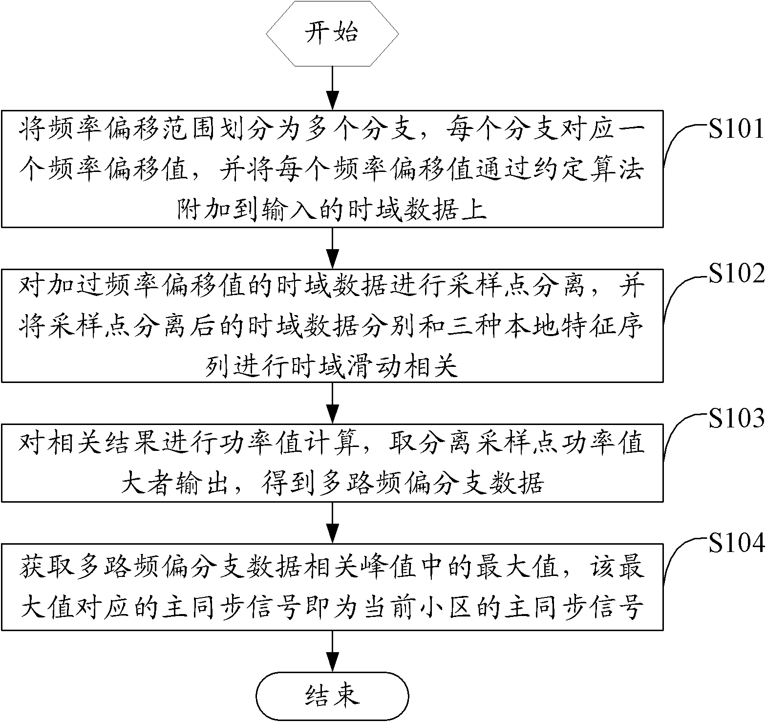
[0048] The core of the embodiment of the present invention is to avoid the influence of a large frequency offset on the synchronization accuracy and the detection performance of the main synchronization signal without prior information, to add the frequency offset to the input data, and to add the additional frequency offset The input signal and the local feature sequence are slidingly correlated to realize the calculation of the position of the primary synchronization signal and the initial estimation of the frequency offset.

[0049] Taking the TDD LTE system as an example below, the technical solution of the present invention will be described in detail in conjunction with the accompanying drawings and implementation modes.

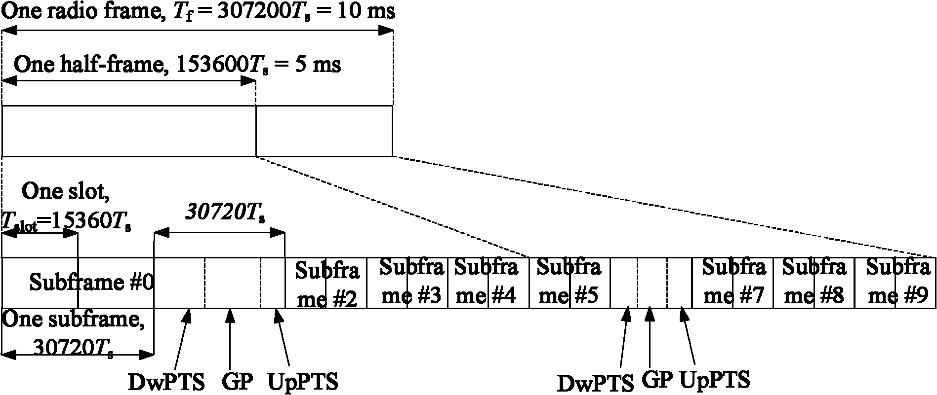
[0050] Such as figure 1 As shown, it is the frame format of TDD LTE, and the 1st and 6th subframes are used for special subframes. The sending period of the main synchronization signal is 5ms, and the contents sent in the two half-frames before and af...


PUM


Abstract

The invention relates to a method, device and terminal for detecting a long term evolution (LTE) master synchronizing signal. In the method, frequency shift range is divided into a plurality of branches, each branch corresponds to a frequency shift value, and each frequency shift value is attached to input time domain data by a coordinated rotation digital computer algorithm; the time domain data with frequency shift value is subjected to sampling point separation, and time domain data subjected to the sampling point separation is respectively subjected to time domain slippage correlation with three local characteristic sequences; power value calculation is carried out on the correlation results, and the separated sampling points with big power value are output so as to obtain multichannel frequency shift branch data; and the maximum value in peak values related to multichannel frequency shift branch data is acquired, the master synchronizing signal corresponding to the maximum value is the master synchronizing signal of the current cell, and the frequency shift value corresponding to the maximum value is an initial frequency shift estimation value. According to the invention, the detection success rate of a master synchronizing signal position is greatly improved, the range of detecting the frequency shift is enlarged, the system resources are reduced, and the implementation is convenient.

Description

technical field [0001] The present invention relates to the field of communication technologies, in particular to a method, device and terminal for detecting an LTE (Long Term Evolution, long term evolution) primary synchronization signal. Background technique [0002] The LTE system is a standardized next-generation wireless communication technology that uses a Constant Envelope Zero Autocorrelation (CAZAC) sequence for a primary synchronization signal. [0003] In the traditional cell primary synchronization signal search scheme, the local characteristic sequence is usually used to perform sliding correlation with the received signal, and then the correlation peak is detected to obtain the location of the primary synchronization signal. [0004] This prior art has the following disadvantages: when the crystal oscillator deviation between transceivers is small, the constant envelope zero autocorrelation sequence has a very good correlation in the time domain, so that the co...

Claims


Application Information

Patent Timeline
Patent Type & Authority Applications(China)
IPC IPC(8): H04B17/00H04B7/26H04L25/03H04L25/02
Inventor 汪宏志
Owner SANECHIPS TECH CO LTD
Why Eureka
Try Eureka