Method for manufacturing high-silicon steel thin strip
A manufacturing method and high-silicon steel technology, applied in the field of strip steel rolling, can solve the problems of not giving texture characteristics and increasing magnetic induction intensity, and achieve the effects of easy industrial application, optimization of recrystallized texture, and high magnetic permeability
- Summary
- Abstract
- Description
- Claims
- Application Information
AI Technical Summary
Problems solved by technology
Method used
Image

Examples
Embodiment 1
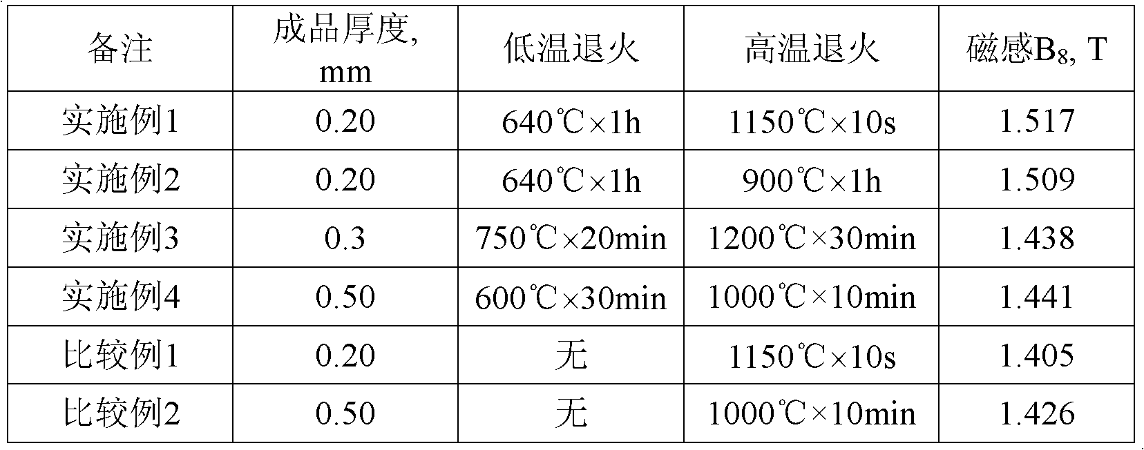
[0028] The high-silicon steel whose composition is shown in Table 1 was smelted in an intermediate frequency induction furnace and cast into ingots. After the ingot is homogenized at 1200°C for 1 hour, it is forged into a slab with a thickness of 60 mm. The slab is continuously hot-rolled to 1.1mm in the range of 1100-700°C. The hot-rolled sheet is subjected to normalization annealing and pickling at 1050°C for 10 minutes, and then cold-rolled to 0.20mm between 400°C and room temperature. The cold-rolled thin strip is first annealed at low temperature at 640°C for 1 hour, and then annealed at high temperature at 1150°C for 10 seconds to obtain the magnetic induction B of the high-silicon steel strip. 8 It is 1.517T.
[0029] Table 1 Chemical composition of experimental steel (mass percentage)
[0030] Si
Embodiment 2
[0032] The high-silicon steel whose composition is shown in Table 1 was smelted in an intermediate frequency induction furnace and cast into ingots. After the ingot is homogenized at 1200°C for 1 hour, it is forged into a slab with a thickness of 60 mm. The slab is continuously hot-rolled to 1.1mm in the range of 1100-700°C. The hot-rolled sheet is subjected to normalization annealing and pickling at 1050°C for 10 minutes, and then cold-rolled to 0.20mm between 400°C and room temperature. The cold-rolled thin strip is first annealed at a low temperature at 640°C for 1 hour, and then at a high temperature at 900°C for 1 hour to obtain the magnetic induction B of the high-silicon steel strip. 8 It is 1.509T.
Embodiment 3
[0034] The high-silicon steel whose composition is shown in Table 1 was smelted in an intermediate frequency induction furnace and cast into ingots. After the ingot is homogenized at 1200°C for 1 hour, it is forged into a slab with a thickness of 60mm. The slab is continuously hot-rolled to 0.9mm in the range of 1100-680°C. The hot-rolled sheet is subjected to normalization annealing at 950°C for 20 minutes and pickling, and then cold-rolled to 0.30mm between 400°C and room temperature. The cold-rolled thin strip is first annealed at a low temperature at 750°C for 20 minutes, and then annealed at a high temperature at 1200°C for 30 minutes to obtain the magnetic induction B of the high-silicon steel strip. 8 It is 1.438T.
PUM
| Property | Measurement | Unit |
|---|---|---|
| Magnetic sense | aaaaa | aaaaa |
| Magnetic sense | aaaaa | aaaaa |
| Magnetic sense | aaaaa | aaaaa |
Abstract
Description
Claims
Application Information
 - R&D Engineer
- R&D Manager
- IP Professional
- Industry Leading Data Capabilities
- Powerful AI technology
- Patent DNA Extraction
Browse by: Latest US Patents, China's latest patents, Technical Efficacy Thesaurus, Application Domain, Technology Topic.
© 2024 PatSnap. All rights reserved.Legal|Privacy policy|Modern Slavery Act Transparency Statement|Sitemap