Foil stamping device of stamping machine

A bronzing machine and foil-feeding technology, which is applied to printing machines, gold powder printing, rotary printing machines, etc., can solve the problems of low utilization rate of anodized aluminum, waste of consumables, and tension deformation of anodized aluminum, so as to improve speed and production efficiency, overcome The effect of low utilization rate of consumables and improvement of utilization rate

Inactive Publication Date: 2011-07-20
HEBEI YUTIAN XINGYE PRINTING MACHINERY
View PDF3 Cites 6 Cited by
  • Summary
  • Abstract
  • Description
  • Claims
  • Application Information

AI Technical Summary

Problems solved by technology

Hot stamping can only be done at a fixed position when foil is being fed, and the utilization rate of anodized aluminum is low, resulting in waste of consumables
Moreover, it is difficult to realize the synchronous release and retraction of the anodized aluminum foil circuit during high-acceleration foil feeding, which can easily cause tension deformation of the anodized aluminum foil, thus restricting the development of hot stamping machines to high speed

Method used


Image

  • Foil stamping device of stamping machine
  • Foil stamping device of stamping machine
  • Foil stamping device of stamping machine

Examples


Embodiment Construction

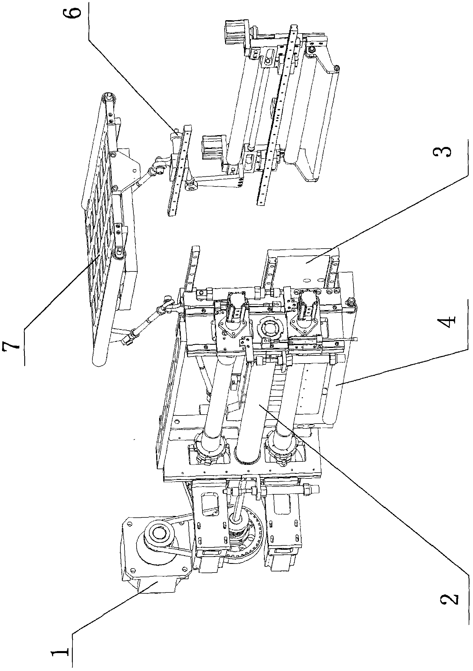
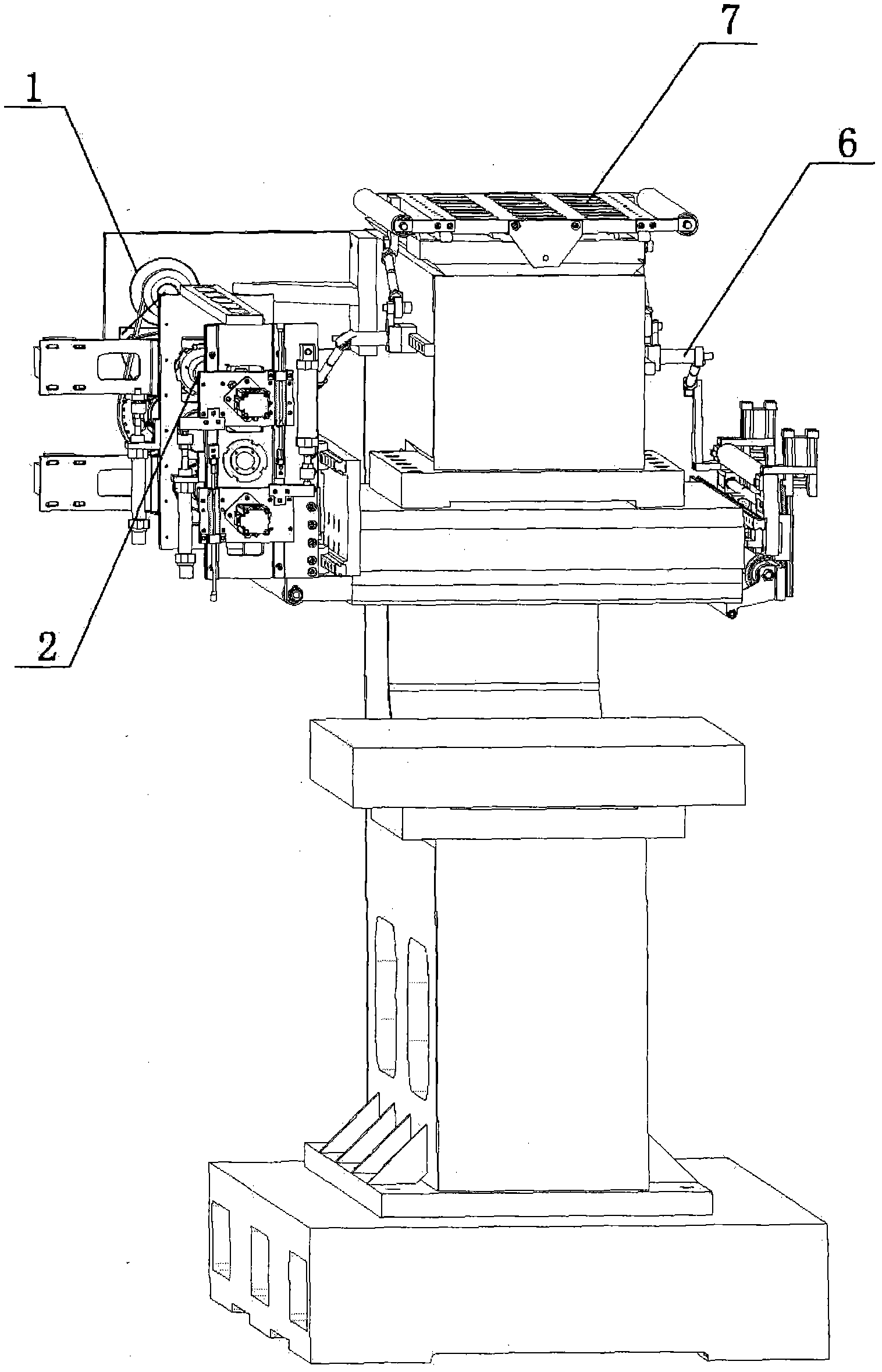
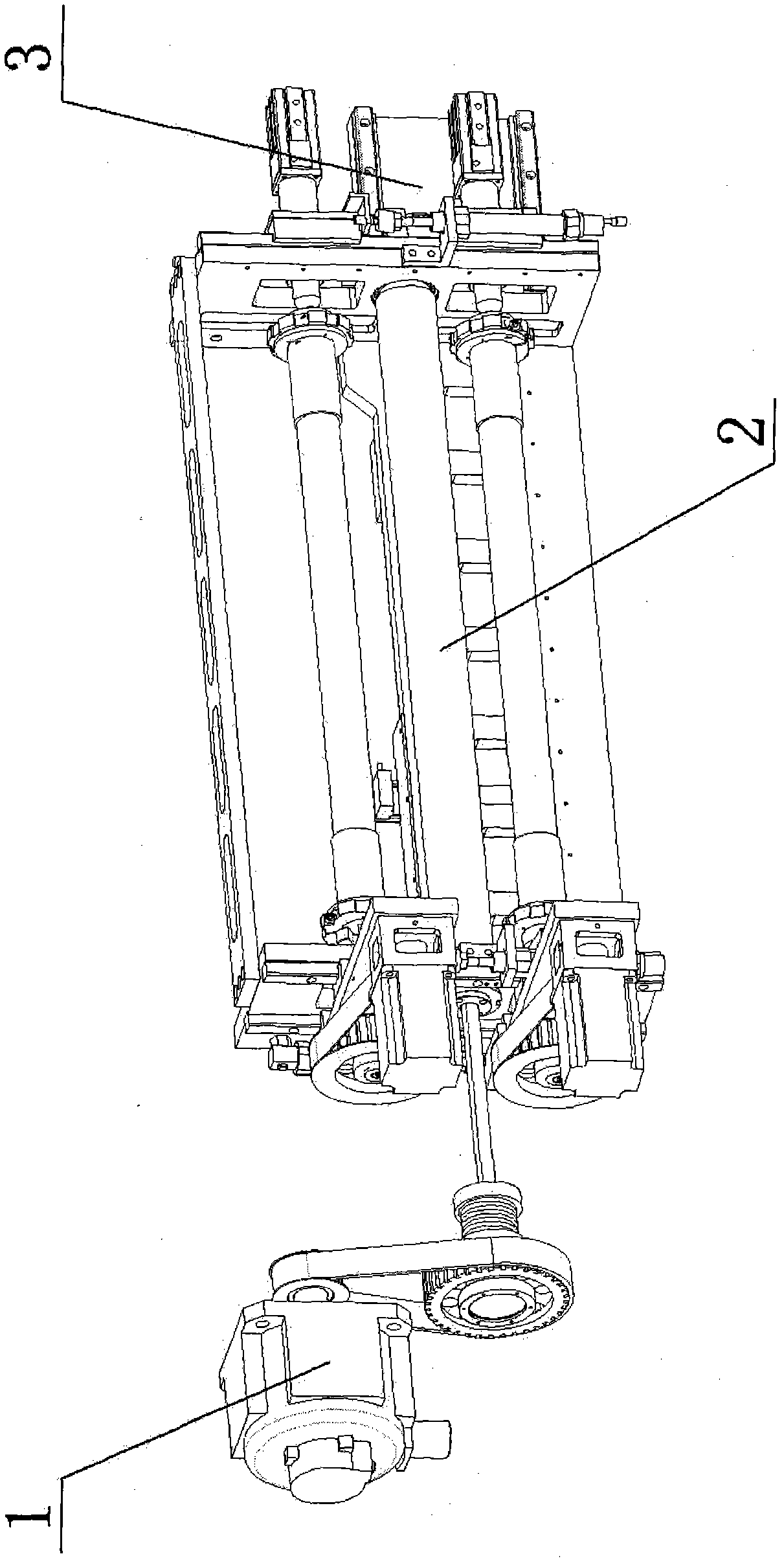
[0022] see Figure 1 to Figure 9 As shown, the present invention is a foil feeding device of a bronzing machine, which consists of a foil feeding drive device 1, a foil feeding linear synchronization device 2, a foil feeding lateral carrying device 3, a foil releasing positioning guide device 4, a guide roller connecting device 6 and Devices such as traversing guide device 7 are formed. Wherein, the foil feeding drive device 1 , the foil feeding linear synchronization device 2 and the foil feeding lateral carrying device 3 jointly form a foil feeding and unwinding device 9 . The traversing guiding device 7 is connected with the foil retracting and unwinding device 9 and drives the entire foil retracting and unwinding device 9 to move laterally; the guide roller connecting device 6 is connected with the traversing guiding device 7 .

[0023] Further, as attached to the manual Figure 4 As shown, the foil feeding driving device 1 includes a first servo motor 11 , a pair of fir...


PUM


Abstract

The invention relates to a foil stamping device of a stamping machine. The foil stamping device comprises a driving device of a stamping foil, a linear synchronization device of the stamping foil, a transverse bearing device of the stamping foil, a positioning and guiding device of an unwinding foil, a guide roller connecting device and a transverse shift guiding device, wherein the driving device of the stamping foil, the linear synchronization device of the stamping foil, and the transverse bearing device of the stamping foil together form a foil winding/unwinding device; the transverse shift guiding device is connected with the foil winding/unwinding device, and drives the whole foil winding/unwinding device to move transversely; and the guide roller connecting device is connected with the transverse shift guiding device. As the foil stamping device of the stamping machine adopts an automatic foil winding/unwinding synchronization structure, the foil stamping speed is greatly accelerated, and the production efficiency is improved; meanwhile, as a transverse foil stamping method is adopted, the utilization rate of consumables is improved, and the cost is saved.

Description

【Technical field】 [0001] The invention relates to an assembly of a hot stamping machine, in particular to a foil feeding device of a hot stamping machine, and belongs to the technical field of printing equipment. 【Background technique】 [0002] The foil releasing part and the foil receiving part in the existing electric aluminum foil feeding device of hot stamping machines are mostly two sets of independent and fixed systems. Hot stamping can only be done at a fixed position when foil is being fed, and the utilization rate of anodized aluminum is low, resulting in a waste of consumables. Moreover, it is difficult to realize the synchronous release and retraction of the anodized aluminum foil circuit during high-acceleration foil feeding, which can easily cause tension deformation of the anodized aluminum foil, thus restricting the development of hot stamping machines to high speed. [0003] Therefore, in order to avoid the above technical problems, it is indeed necessary to...

Claims


Application Information

Patent Timeline
Patent Type & Authority Applications(China)
IPC IPC(8): B41F13/02B41F19/06B41G1/00
Inventor 葛绍君徐景方张红川王爱平唐志全胡占军杜金源
Owner HEBEI YUTIAN XINGYE PRINTING MACHINERY
Why Eureka
Try Eureka