
Aircraft landing gear drop lifting force simulating device

A technology of aircraft landing gear and lift, applied in the direction of measuring devices, aircraft parts, ground devices, etc., can solve the problems of excessive lift and vibration of lift, and achieve the effect of light weight, easy processing, and meeting the requirements of strength and fatigue

Inactive Publication Date: 2011-07-20
NANJING UNIV OF AERONAUTICS & ASTRONAUTICS
View PDF5 Cites 16 Cited by
  • Summary
  • Abstract
  • Description
  • Claims
  • Application Information

AI Technical Summary

Problems solved by technology

[0003] Purpose of the invention: To design an imitation lift system that can accurately simulate the landing lift of an aircraft, which can satisfy the real simulation of the landing imitation lift of different aircraft in the landing gear impact test, and solve the problem of excessive lift and lift oscillation caused by the inertial load of the piston rod of the imitation lift cylinder

Method used


Image

  • Aircraft landing gear drop lifting force simulating device
  • Aircraft landing gear drop lifting force simulating device

Examples


Embodiment Construction

[0014] Below in conjunction with accompanying drawing, the present invention is described in further detail:

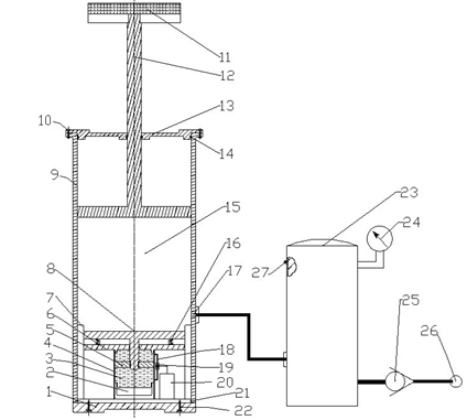
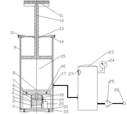
[0015] Such as figure 1 Shown: Aircraft landing gear shock imitation lift device, in the figure 1 is the base of the actuator, 2 is the compensator, 3 is the magnetorheological fluid, 4 is the magnetorheological sleeve, 5 is the lower plate of the damping piston rod , 6 is the upper cover of the shock absorber, 7 is the damping sleeve, 8 is the damping piston, 9 is the sleeve of the actuator, 10 is the bolt of the upper cover of the actuator, 11 is the rubber layer, and 12 is the bionic actuator Piston rod, 13 is the upper cover of the actuator, 14 is the sealing ring, 15 is the compressed air chamber, 16 is the return spring, 17 is the air inlet, 18 is the damping tube, 19 is the control single-stage coil, 20 is the spring coil, 21 is a sealing ring, 22 is a base bolt, 23 is an accumulator, 24 is a pressure gauge, 25 is a check valve, 26 is an air compression pump, ...


PUM


Abstract

The invention relates to an aircraft simulating device, in particular to an aircraft landing gear drop test lifting force simulating device. In the invention, a damping piston is arranged in a damping sleeve, the damping sleeve is arranged in an actuator cylinder, and the actuator cylinder is externally connected with a power accumulator; and the power accumulator is aerated through an air pump and provides lifting power for the actuator cylinder to simulate lifting force. In the invention, the piston rod of the lifting force simulating actuator cylinder is made of an aluminum alloy material and has the advantages of compact structure, light weight and high strength; the structure of the lifting force simulating system is reliable in a running process, which effectively simulates the lifting force; and the device has the advantages of simple and reliable structure, easy processing and low economic cost and is easy to meet the requirement on strength and fatigue.

Description

technical field [0001] The invention relates to an aircraft simulation device, in particular to an aircraft landing gear drop shock test imitation lift. Background technique [0002] In order to ensure the safety of the aircraft landing, the aircraft usually sinks at a certain speed V y Perform a floating landing where the wing lift is generally equal to the landing weight of the aircraft. In order to simulate the influence of wing lift on the landing load of the aircraft when the aircraft lands, there are two internationally accepted landing gear drop test methods: the free drop test based on energy equivalent without imitation lift and weight reduction method specified by the US military standard, and Drop test with mechanical imitation lift performed by Russian norms. The mechanical imitation lift has two ways: a rubber rope imitation lift and an air cylinder imitation lift. The rubber rope imitation lift uses the tensile deformation yield section of the rubber rope to...

Claims


Application Information

Patent Timeline
Patent Type & Authority Applications(China)
IPC IPC(8): B64F5/00G01M7/08B64F5/60
Inventor 薛彩军戚文刚谭伟聂宏孙滨蒋文涛
Owner NANJING UNIV OF AERONAUTICS & ASTRONAUTICS
Learn More