Five-phase permanent magnet fault-tolerant motor with magnetic congregating effect for electric vehicle

An electric vehicle and permanent magnet fault-tolerant technology, which is applied in the fields of electric vehicles, electricians, and motors, can solve the problems of reducing the fault-tolerant performance of the motor, interphase short circuit, and difficulty in weakening the magnetic speed regulation, so as to save the mechanical connection and save the motor Effect of reducing cost and motor weight

Inactive Publication Date: 2011-07-20
JIANGSU UNIV
View PDF2 Cites 14 Cited by
  • Summary
  • Abstract
  • Description
  • Claims
  • Application Information

AI Technical Summary

Problems solved by technology

Hub permanent magnet motor with outer rotor structure as attached figure 1 As shown, the outside of the motor is the outer rotor 3, the middle is the stator 1, and the armature teeth 4 are between the outer rotor 3 and the stator core 1. The motor mechanism has a large torque-to-mass ratio and can provide a large rotational speed At the same time, the quality of the whole vehicle is reduced, but the motor has the following disadvantages: First, because the permanent magnet 3 of the motor is surface-mounted, and the permanent magnet 3 is attached to the inner surface of the outer rotor 2, the equivalent air gap of the motor Larger, it is difficult to achieve weak magnetic speed regulation; secondly, the motor adopts double-layer distributed winding 6, in the case of reasonable arrangement of the winding span, although the isolation of the magnetic circuit of the motor can be achieved, the windings of different phases are distributed in the same slot , so that the motor structure will inevitably appear phase-to-phase short circuit, which greatly reduces the fault tolerance performance of the motor

Method used


Image

  • Five-phase permanent magnet fault-tolerant motor with magnetic congregating effect for electric vehicle
  • Five-phase permanent magnet fault-tolerant motor with magnetic congregating effect for electric vehicle
  • Five-phase permanent magnet fault-tolerant motor with magnetic congregating effect for electric vehicle

Examples


Embodiment Construction

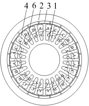
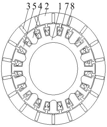
[0018] Such as figure 2 As shown, the present invention is a five-phase, outer rotor, permanent magnet built-in motor structure, which is composed of a stator 1, an outer rotor 2, a permanent magnet 3, an armature tooth 4, a fault-tolerant tooth 5 and a single-layer concentrated winding 7 . The iron cores of the stator 1 and the outer rotor 2 are formed by laminating punched sheets of D23 material commonly used in China.

[0019] The outer rotor 2 is arranged on the outer ring of the stator 1, and the armature teeth 4 and the fault-tolerant teeth 5 are arranged between the outer rotor 2 and the stator 1. The armature teeth 4 and the fault-tolerant teeth 5 are evenly distributed along the outer ring of the stator 1, and the armature The teeth 4 and the tolerance teeth 5 are arranged at intervals one by one, and the width of the armature teeth 4 is twice the width of the tolerance teeth 5 . The permanent magnets 3 are radially embedded in the outer rotor 2 along the circumfer...


PUM


Abstract

The invention discloses a five-phase permanent magnet fault-tolerant motor with a magnetic congregating effect for an electric vehicle. An outer rotor is arranged on a stator outer ring, armature teeth and fault-tolerant teeth are uniformly distributed at intervals along the circumferential direction of the stator outer ring, permanent magnets are uniformly and radially embedded in the direction of the circumference in the outer rotor, a single-layer concentrated winding is wound on the armature teeth, radially opposite dipolar single-layer concentrated windings are serially connected to form one phase; total tooth quantity of the armature teeth and the fault-tolerant teeth is a multiple of 10 and is not equal to the quantity of permanent magnets, and the difference of the total tooth quantity of the armature teeth and the fault-tolerant teeth does not exceed +/-4; rotor grooves with same quantity as the permanent magnets are arranged on the outer rotor and positioned between each of the permanent magnets and the stator; and the width of the armature teeth is two times of that of the fault-tolerant teeth. The flux leakage of the permanent magnets is reduced while a magnetic-gathering effect is generated, the consumption of the permanent magnets is reduced, the motor cost is saved, the motor weight is reduced, and the reliability and the failure operation capacity of the motor is improved.

Description

technical field [0001] The invention relates to the technical fields of electrician, motor and electric vehicle, in particular to a five-phase permanent magnet fault-tolerant motor used for electric vehicles. Background technique [0002] In recent years, the use of electric vehicles has become one of the ways to solve the energy crisis and environmental pollution. The drive motor is the core component of an electric vehicle, and the performance of the drive motor is a key factor determining the efficiency and performance of an electric vehicle. [0003] With the emergence of permanent magnet materials with high magnetic energy product, permanent magnet motors are widely used in military affairs, industrial and agricultural production and daily life. Compared with traditional electrically excited motors, permanent magnet motors have significant advantages such as simple structure, reliable operation, small size, light weight, low loss, high efficiency, and flexible and diver...

Claims


Application Information

Patent Timeline
Patent Type & Authority Applications(China)
IPC IPC(8): H02K21/22H02K1/27H02K3/28H02K1/14
CPCY02T10/641Y02T10/64
Inventor 刘国海陈前赵文祥龚文胜张多蒋彦
Owner JIANGSU UNIV
Why Eureka
Try Eureka