Speed-sensor-less construction method for detecting rotating speed of bearing-less asynchronous motor

A speed sensorless, asynchronous motor technology, applied in the control of generators, motor generators, electromechanical brakes, etc., can solve the problems of poor identification accuracy, lack of parameter configuration, large identification errors, etc., and achieve simple control methods and reduce Cost, effect of utility structure

Inactive Publication Date: 2011-07-20
JIANGSU UNIV
View PDF4 Cites 10 Cited by
  • Summary
  • Abstract
  • Description
  • Claims
  • Application Information

AI Technical Summary

Problems solved by technology

Among them, the direct estimation method is greatly affected by noise interference and motor parameter errors; the Kalman filter method uses the minimum variance optimal prediction estimation method to weaken random interference and measurement noise, but the algorithm is complex, the parameter configuration lacks certain standards, and the amount of calculation is large ; The high-frequency harmonic signal injection method estimates the speed, which can improve its low-speed performance, but it is greatly affected by the motor load; the MARS method based on voltage and current has poor identification accuracy due to the existence of a pure integral link, and is affected by the stator resistance. Stable; the MARS method based on the back EMF can solve the pure integral problem, but the identification error is large when the speed crosses zero; the MARS method based on the instantaneous reactive power model is not affected by the stator resistance, but the speed is unstable when the speed is given as a negative step

Method used


Image

  • Speed-sensor-less construction method for detecting rotating speed of bearing-less asynchronous motor
  • Speed-sensor-less construction method for detecting rotating speed of bearing-less asynchronous motor
  • Speed-sensor-less construction method for detecting rotating speed of bearing-less asynchronous motor

Examples


Embodiment Construction

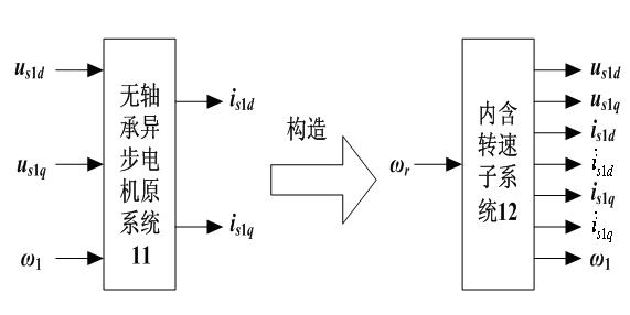
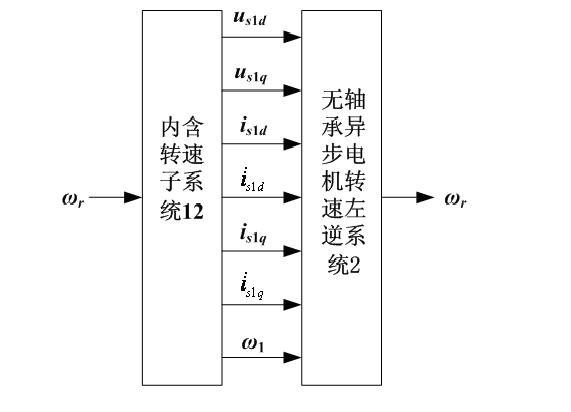
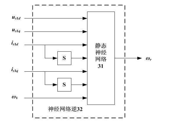
[0015] See Figure 1-4 , The present invention first establishes a mathematical model containing the rotational speed subsystem 12 based on the mathematical model of the original system 11 of the bearingless asynchronous motor. The input and output of the rotational speed subsystem 12 satisfy the mathematical model of the original system 11 of the bearingless asynchronous motor. The variable constraint relationship determined by the model; then an inverse model containing the speed subsystem 12 is established, that is, the bearingless asynchronous motor speed left inverse system 2; and then a static neural network 31 with 7 input nodes and 1 output node and 2 The differentiator S constitutes a neural network inverse 32 with five input nodes and one output node, which contains the rotational speed subsystem 12; and by adjusting the weights of the static neural network 31, the neural network inverse 32 realizes the rotational speed of the bearingless asynchronous motor. The functi...


PUM


Abstract

The invention discloses a speed-sensor-less construction method for detecting the rotating speed of a bearing-less asynchronous motor, which comprises the following steps: constructing a mathematical model containing a rotating speed subsystem for the original bearing-less asynchronous motor system; establishing a bearing-less asynchronous motor rotating speed left-inverse system containing a rotating speed subsystem; adopting a static neural network and two differentiators S to form a neural network inverse model; training the static neural network; adjusting and determining all weight coefficients of the static neural network so as to achieve the bearing-less asynchronous motor rotating speed left-inverse system; and finally, inversely connecting the static neural network with the back side of the original bearing-less asynchronous motor system in series so as to finish the speed-sensor-less construction. By omitting a photoelectric coder and an interface circuit thereof of the original system, the invention lowers the cost for controlling the system, can carry out high-accuracy control fast and accurately, has high adaptivity, robustness and error tolerance, and has higher generalization capability and adaptive capability.

Description

Technical field [0001] The invention belongs to the technical field of electric drive control equipment. It is a speed sensorless construction method for quickly and accurately detecting the rotation speed of a bearingless asynchronous motor. It provides a new control method for the speedless operation of a bearingless asynchronous motor and is suitable for bearingless asynchronous motors. High-performance control of asynchronous motors. Background technique [0002] The bearingless asynchronous motor is a nonlinear strong coupling system. In order to achieve the decoupling control of torque and suspension force, field-oriented control is generally used. This control method needs to detect the speed of the rotor, obtain the precise spatial position of the magnetic flux required for field orientation, realize the decoupling control between the torque and the suspension force, and ensure the stable suspension operation of the rotor. Traditional motor speed measurement devices most...

Claims


Application Information

Patent Timeline
IPC IPC(8): H02P21/00H02P21/14H02P21/18H02P21/24
Inventor 杨泽斌孙晓东张婷婷朱熀秋
Owner JIANGSU UNIV
Why Eureka
Try Eureka