Casting method of aluminum alloy rod parts and casting equipment for realizing same

An aluminum alloy and equipment technology, applied in the casting field of aluminum alloy parts, can solve problems such as poor quality consistency of blanks, inability to fill local cavities, increase energy consumption of molten metal, etc., so as to improve product manufacturing efficiency, good solidification consistency, The effect of eliminating air slag holes

Inactive Publication Date: 2011-07-27
ZHEJIANG HENGTONG MACHINERY
View PDF0 Cites 5 Cited by
  • Summary
  • Abstract
  • Description
  • Claims
  • Application Information

AI Technical Summary

Problems solved by technology

There are two commonly used casting methods for aluminum alloy bar parts. One is inclined top casting, in which the mold is tilted, and the aluminum alloy metal liquid is poured directly from the top of the cavity. After the metal liquid fills the cavity, the mold is vertical. After the molten metal is cooled in the cavity, it is taken out to become a part blank. In this casting method, oxide skin will be produced due to oxidation during the process of pouring the molten metal into the cavity. The oxide scale has a large area and is easy to generate and accumulate under the oxide skin. Air bubbles affect the product quality. When the surface shape of the part is relatively complex, it is easy to ca

Method used


Image

  • Casting method of aluminum alloy rod parts and casting equipment for realizing same
  • Casting method of aluminum alloy rod parts and casting equipment for realizing same
  • Casting method of aluminum alloy rod parts and casting equipment for realizing same

Examples


Embodiment Construction

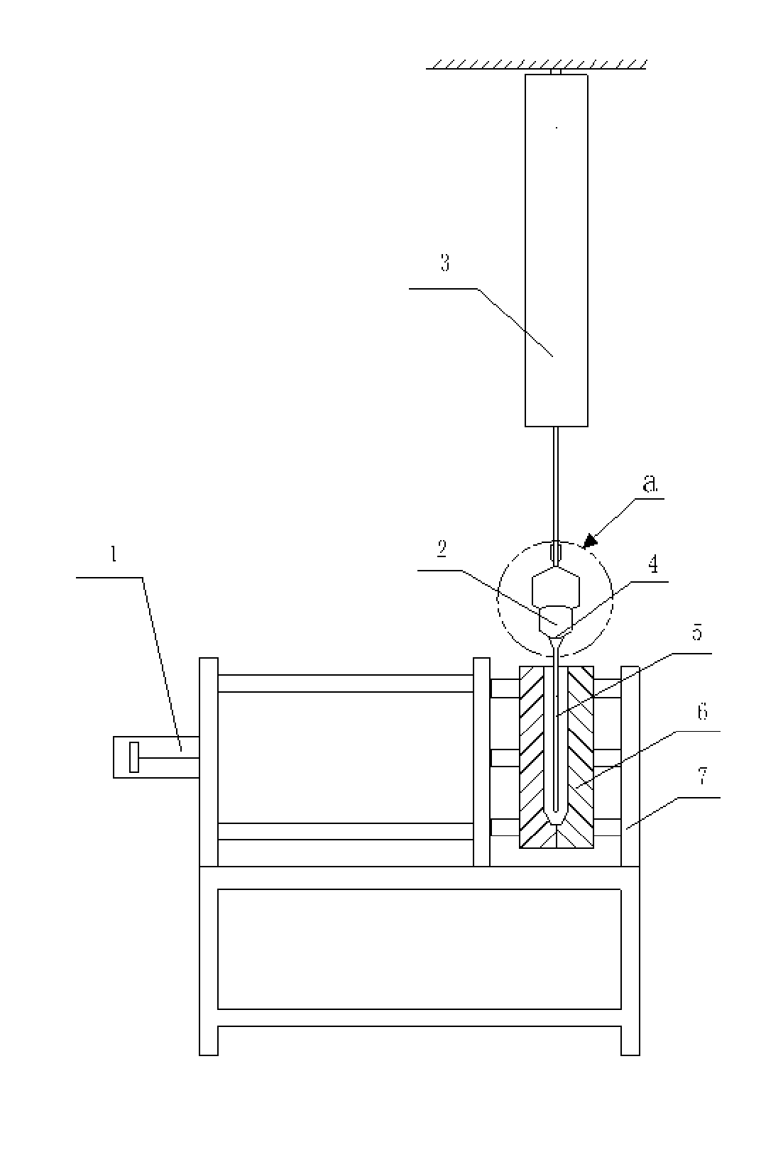
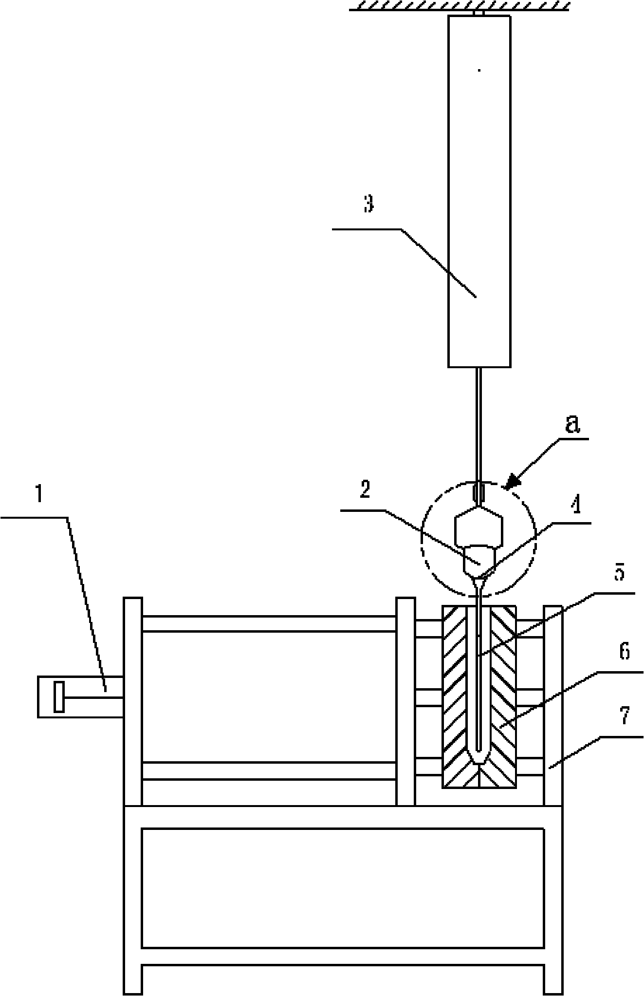
[0022] The method of the present invention adopts a casting method in which liquid is supplied under the liquid surface and the molten metal is cooled and solidified sequentially from bottom to top. The infusion tube is connected to the bottom of the container and inserted into the bottom of the mold cavity, and the molten metal is injected into the cavity through the infusion tube. The metal liquid overflows the liquid outlet at the bottom of the infusion tube to form a submerged liquid supply. The premise is that it is located below the liquid metal liquid level and gradually rises relative to the bottom of the cavity, and the liquid metal liquid level gradually rises relative to the bottom of the cavity and is sequentially cooled and solidified from the bottom to the top of the cavity.

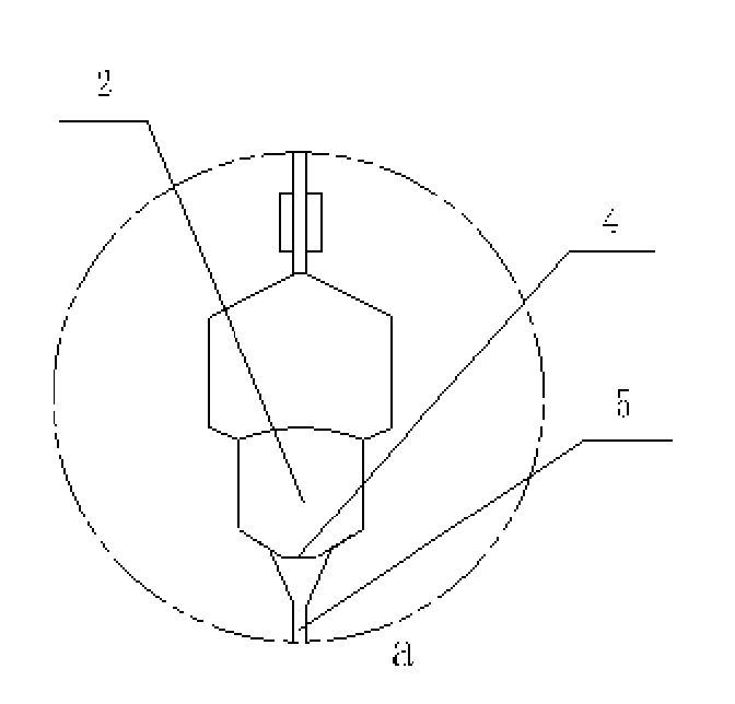
[0023] Specific embodiments of the present invention will be described in detail below in conjunction with the accompanying drawings.

[0024] Such as figure 1 , figure 2 As shown, the c...


PUM


Abstract

The invention relates to a casting method of aluminum alloy rod parts and casting equipment for realizing the same. The casting method is characterized in that liquid supply is carried out under the liquid level and a metal liquid is cooled and solidified from bottom to top. The casting equipment comprises a mould and a suspended funnelform ladle, wherein the mould is arranged with a mould cavity opening vertically upward; a filter screen is padded at the bottom of the inner cavity of the ladle; the inner cavity of the ladle and a funnel opening are partitioned by the filter screen; the meshes of the filter screen are fine, thereby temporarily storing molten metal foams; the funnel opening of the ladle is connected with a long and thin liquid conveying pipe for guiding and conveying molten metal; the liquid conveying pipe is inserted into the mould cavity of the mould and the bottom end of the liquid conveying pipe is close to the bottom of the mould cavity; the molten metal is injected to the mould cavity through the liquid conveying pipe; the liquid conveying pipe raises gradually relative to the bottom of the mould cavity on the premise that the bottom liquid outlet of the liquid conveying pipe is positioned below the liquid level after the molten metal overflows the bottom of the liquid conveying pipe, and the liquid level gradually raises and is sequentially cooled and solidified towards the top. By utilizing the casting method, the defects of poor quality, low molded product percent of pass and high energy consumption existing in the traditional casting method are overcome, and low energy consumption, high part percent of pass and good quality are realized.

Description

technical field [0001] The invention belongs to the technical field of casting aluminum alloy parts, and in particular relates to a casting method of aluminum alloy bar parts and equipment for realizing the method. Background technique [0002] Aluminum alloy bar parts such as motorcycle shock absorber sleeves are casted. After the casting mold is closed, a casting cavity is formed. Since the cast parts are bars, the axial length of the cavity is relatively large. There are two commonly used casting methods for aluminum alloy bar parts. One is inclined top casting, in which the mold is tilted, and the aluminum alloy metal liquid is poured directly from the top of the cavity. After the metal liquid fills the cavity, the mold is vertical. After the molten metal is cooled in the cavity, it is taken out to become a part blank. In this casting method, oxide skin will be produced due to oxidation during the process of pouring the molten metal into the cavity. The oxide scale has a...

Claims


Application Information

Patent Timeline
IPC IPC(8): B22D21/04B22D9/00
Inventor 石孟成
Owner ZHEJIANG HENGTONG MACHINERY
Why Eureka
Try Eureka