
Current-mode current induction circuit externally connected with MOS (metal oxide semiconductor) and method for realizing current mode

A flow sensing part, current mode technology, applied in the field of power switch control, can solve the problems of poor input change suppression ability, insensitive output change adjustment response, etc., to eliminate sub-harmonic instability, adjust flexibility, and reduce complexity. Effect

Active Publication Date: 2011-08-03
CHIPHOMER TECH SHANGHAI
View PDF5 Cites 17 Cited by
  • Summary
  • Abstract
  • Description
  • Claims
  • Application Information

AI Technical Summary

Problems solved by technology

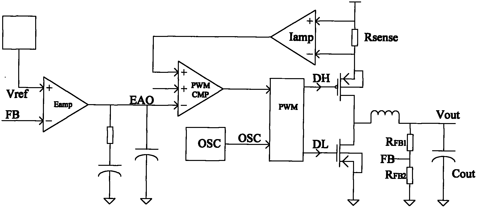
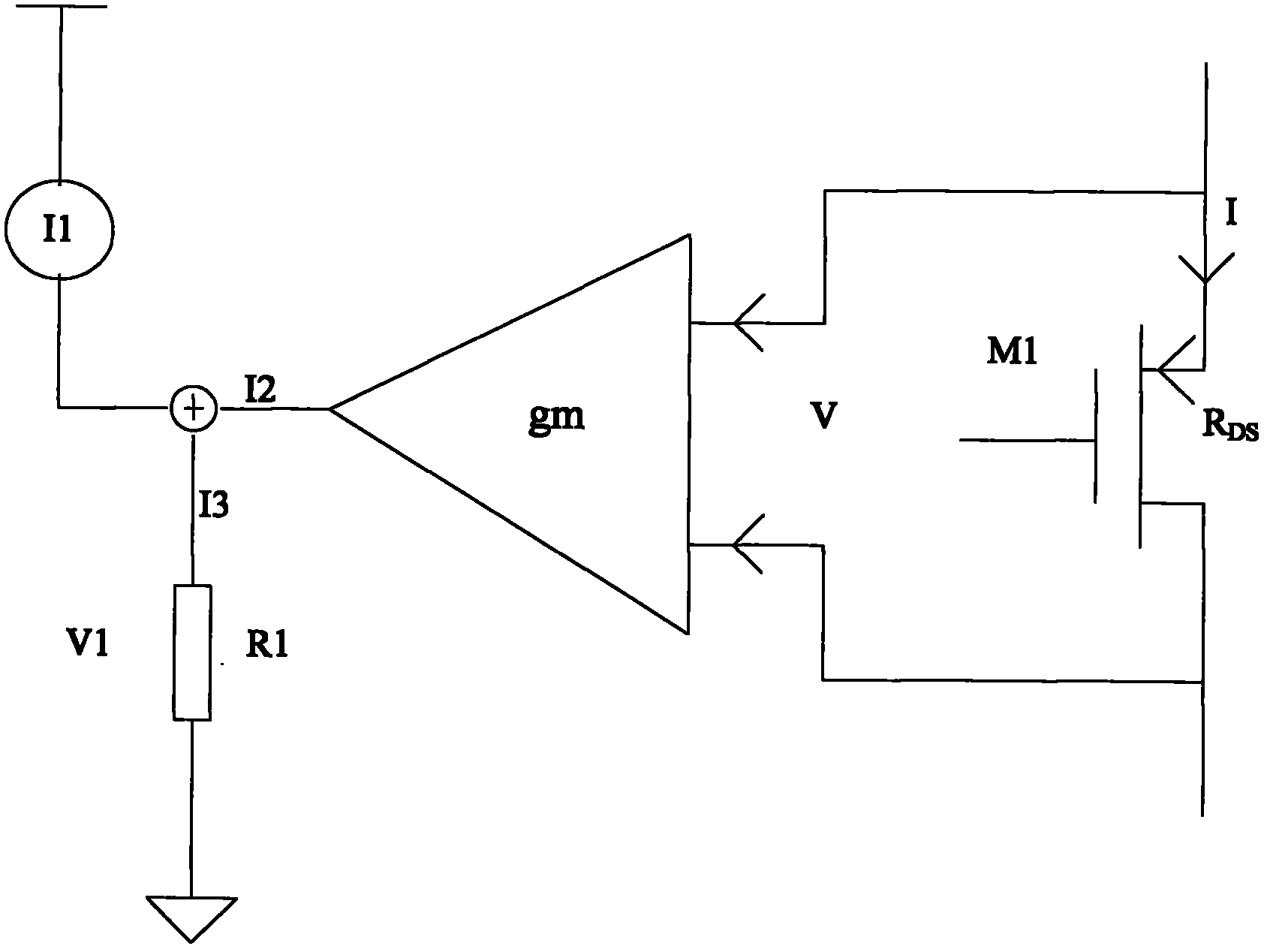
[0019] The purpose of the present invention is to provide a current mode current sensing circuit suitable for external MOS, to solve the problem that the traditional external MOS tube design is limited by the change of internal resistance of the MOS tube and adopts the voltage control mode, and the voltage control mode is not sensitive to the adjustment of the output change. , and the technical problem of poor ability to suppress input changes

Method used


Image

  • Current-mode current induction circuit externally connected with MOS (metal oxide semiconductor) and method for realizing current mode
  • Current-mode current induction circuit externally connected with MOS (metal oxide semiconductor) and method for realizing current mode
  • Current-mode current induction circuit externally connected with MOS (metal oxide semiconductor) and method for realizing current mode

Examples


Embodiment Construction

[0052] Several preferred embodiments of the present invention will be described in detail below with reference to the accompanying drawings, but the present invention is not limited to these embodiments. The present invention covers any alternatives, modifications, equivalent methods and schemes made on the spirit and scope of the present invention. In order to provide the public with a thorough understanding of the present invention, specific details are set forth in the following preferred embodiments of the present invention, but those skilled in the art can fully understand the present invention without the description of these details. In addition, well-known methods, procedures, procedures, components, circuits, etc. have not been described in detail in order to avoid unnecessary confusion to the essence of the present invention.

[0053] The core idea of ​​the present invention is to compensate the change of the on-resistance value of the external MOS transistor through...


PUM


Abstract

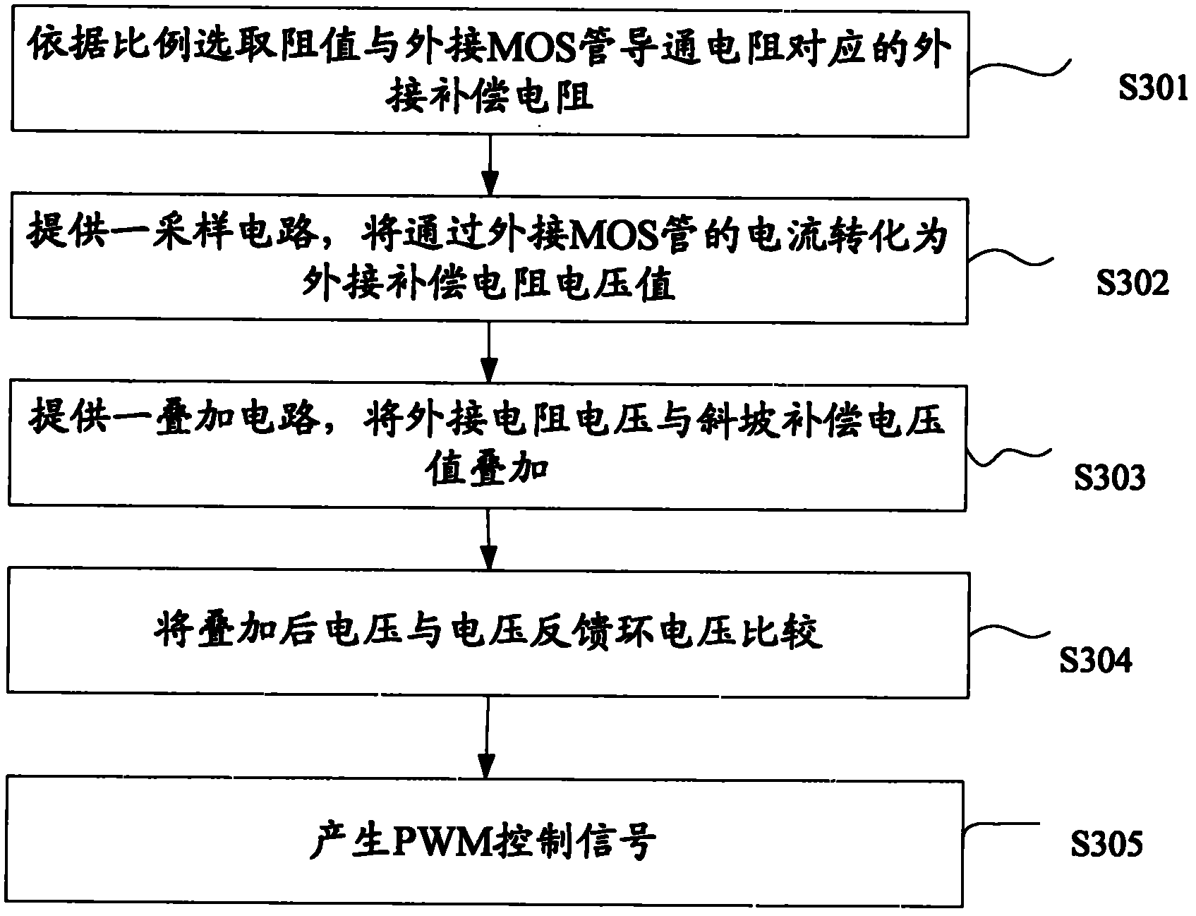
The invention provides a current-mode current induction circuit externally connected with a power MOS (metal oxide semiconductor) transistor and a method for realizing the current mode. The current induction circuit further comprises a current sampling circuit, an adjustable external compensating resistor and a superposed circuit, wherein the current sampling circuit is used for converting the current flowing through the MOS transistor into voltage on the external resistor; the superposed circuit is used for superposing the voltage on the external resistor with the slope compensation voltage;and the resistance value of the external compensating resistor is set according to the on resistance of the external MOS transistor. The circuit and method provided by the invention have the following advantages and positive effects: sampling of the output current of the external MOS transistor can be realized under the current mode and the adjustable external compensating resistor is used for setting the value of the transfer resistance as a fixed value, thus the fixed current compensation slope can be designed to eliminate instability of subharmonics; the technical problem that the technicians in the field can only adopt voltage mode during externally connecting the MOS transistor before is solved; the complexity of loop compensation is reduced; and adjustment is more flexible.

Description

technical field [0001] The invention relates to the field of power switch control, in particular to an externally connected MOS current mode current sensing part circuit. Background technique [0002] The basic working principle of the PWM switch voltage stabilization or current stabilization circuit is that when the input voltage changes, the internal parameters change, and the external load changes, the control circuit performs closed-loop feedback through the difference between the controlled signal and the reference signal to adjust the main circuit switch. The conduction pulse width makes the output voltage or current of the switching power supply and other controlled signals stable. For the PWM closed-loop feedback control system with fixed frequency width modulation, there are mainly five PWM feedback control modes, namely voltage mode control, peak current control mode (also called current mode), average current mode control, hysteresis current mode control and Addi...

Claims


Application Information

Patent Timeline
IPC IPC(8): G05F1/56
Inventor 刘贺白建雄吴珂
Owner CHIPHOMER TECH SHANGHAI
Learn More