Eureka AIR delivers breakthrough ideas for toughest innovation challenges, trusted by R&D personnel around the world.

Grading catalytic combustion device capable of coupling strong and weak heat release

A catalytic combustion, strong and weak technology, applied in the field of reactors, can solve the problems of reducing fuel utilization efficiency, small combustion space, limiting fuel utilization, etc., and achieve the effects of prolonging the fluid movement path, improving combustion efficiency, and reducing heat dissipation

Inactive Publication Date: 2011-08-10
CHONGQING UNIV
View PDF7 Cites 7 Cited by
  • Summary
  • Abstract
  • Description
  • Claims
  • Application Information

AI Technical Summary

Problems solved by technology

However, due to the extremely small combustion space of the micro burner, the residence time of fuel combustion in the combustion chamber is shortened sharply, and it is prone to unstable combustion, difficult ignition, easy flameout, etc., and it is difficult to ensure complete combustion of fuel.
In addition, as the combustion space shrinks, the surface-to-volume ratio of the burner increases, and the heat loss is very serious
Existing burners generally use one of them alone, and rarely combine the two parts for application, which limits the utilization of some fuels and reduces the efficiency of fuel utilization

Method used


Image

  • Grading catalytic combustion device capable of coupling strong and weak heat release
  • Grading catalytic combustion device capable of coupling strong and weak heat release
  • Grading catalytic combustion device capable of coupling strong and weak heat release

Examples


Embodiment Construction

[0015] The present invention will be described in further detail below in conjunction with the accompanying drawings and specific embodiments.

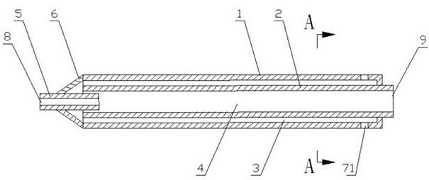
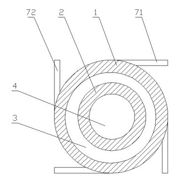
[0016] figure 1 It is a schematic cross-sectional structure diagram of a staged catalytic combustion device coupled with strong and weak heat release of the present invention, figure 2 for figure 1 The cross-sectional view along the A-A direction is shown in the figure. A staged catalytic combustion device that couples strong and weak heat release includes an inner cylinder 2 , an outer cylinder 1 sheathed outside the inner cylinder 2 , a conical sleeve 6 and an air intake circular pipe 5 . One end of the outer cylinder 1 is sealed with the inner cylinder 2, and the other end of the outer cylinder 1 communicates with the inner hole of the inner cylinder 2; one end of the inner cylinder 2 protrudes from the sealed end of the outer cylinder 1, and the protruding end serves as an exhaust port 9. One end of the air inlet pipe 5 extend...


PUM


Abstract

The invention discloses a grading catalytic combustion device capable of coupling strong and weak heat release, which comprises an inner barrel, an outer barrel, a conical sleeve and a circular air inlet pipe; one end of the outer barrel is sealed with the inner barrel; one end of the inner barrel extends out of the sealing end of the outer barrel; the circular air inlet pipe extends into the other end of the inner barrel; the conical sleeve is hermetically connected between the outer barrel and the circular air inlet pipe; a plurality of air inlet pipes communicated with the inside of the outer barrel are uniformly distributed on the circumference of the outer barrel; a gas inlet pipe communicated with the inside of the outer barrel is arranged between the adjacent air inlet pipes; and the inner wall of the outer barrel and the wall of the inner barrel are coated with catalytic agents. The grading catalytic combustion device centralizes the inner barrel and the outer barrel into a reaction device to carry out grading catalytic combustion to generate the coupling reaction, thereby enhancing the oxidation reaction; the air inlet pipes are tangentially and crosswise arranged to facilitate the uniform mixing of gas and air and the adherence flowing; and the retention time of gas swirl in a micro space is increased so as to enhance the combustion stability and ensure that the reaction is easier to generate, the combustion is more complete, and the combustion efficiency is further improved.

Description

technical field [0001] The invention relates to a reactor suitable for gas catalytic reforming combustion, in particular to a novel staged catalytic combustion device coupling strong and weak heat release. Background technique [0002] With the development of science and technology, the application of micro-machines has been paid more and more attention by scientists. Compared with traditional mechanical devices, micro-mechanical devices have incomparable advantages: small size, light weight, can greatly reduce the volume of the device, and complete work that people cannot complete in a small space; high energy density, relatively High working efficiency, the micro-mechanical device can better convert the chemical energy of the fuel into mechanical energy output; the production cost is low, and the pollution to the environment is small. It is precisely because of these advantages that micro-machines have broad application prospects in military, national defense constructi...

Claims


Application Information

Patent Timeline
Patent Type & Authority Applications(China)
IPC IPC(8): F23D14/02F23D14/46
Inventor 闫云飞张力孙志伟冉景煜蒲舸唐强
Owner CHONGQING UNIV
Why Eureka
Eureka Blog
Learn More