Method and device for separating optical crystal by using two laser beams
An optical crystal, laser beam technology, applied in laser welding equipment, metal processing equipment, welding equipment and other directions, to achieve the effect of eliminating pollution damage
- Summary
- Abstract
- Description
- Claims
- Application Information
AI Technical Summary
Problems solved by technology
Method used
Image
Examples
example 1
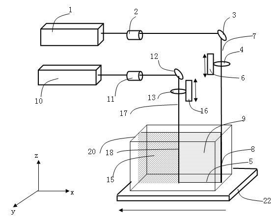
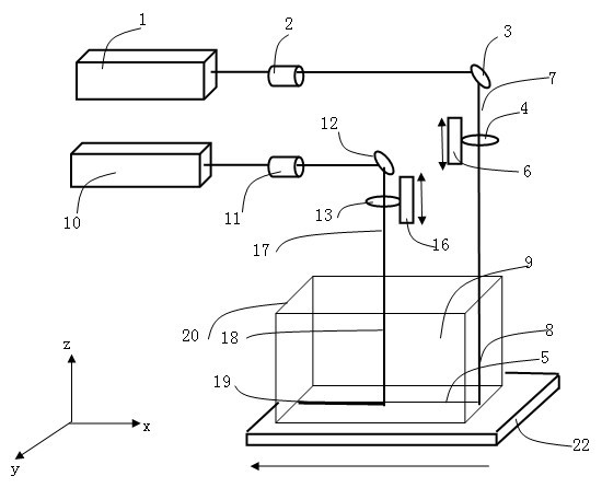
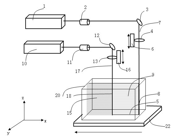
[0044] The present invention adopts a pulse width of 50fs, a wavelength of 800nm, and a maximum pulse peak power of 4×10 11 W. A femtosecond pulse laser with a maximum single pulse energy of 2mJ is used as a high peak power, low energy ultrashort pulse laser beam and a YLR-50 model fiber laser, with an output wavelength of 1070nm, an output peak laser power of 50W, and a pulse energy of 1J As a low peak power, high energy laser beam, the focused spot diameters are 10 μm and 50 μm respectively, and the separated KDP sample size is 60 mm in length and 11.18 mm in thickness. Experimental method: One of the specific implementations of KDP optical crystals is separated by double laser beams, the pulse energy of the femtosecond laser is adjusted to 1mJ, and the pulse peak power is 2×10 11 W, scanning speed 0.6m / min. The output peak power of the fiber laser is 50W, the pulse energy is 1J, and the scanning speed is 1m / min. Experimental results: The optical crystal is separated along...
example 2
[0046] The present invention adopts the UVP266-0.25 type picosecond ultraviolet laser, the output wavelength is 266nm, the pulse width is 15ps, the maximum output single pulse energy is 250nJ, and the highest pulse peak power is 1.7×10 11 The W ultraviolet laser is used as a high peak power, low energy ultrashort pulse laser beam and the YLM-200 model fiber laser, the output wavelength is 1070nm, and the output continuous laser power is 200W as a low peak power, high energy laser beam, and the focus spot diameter is respectively 6μm and 80μm, the size of the separated KDP sample is 40mm in length and 55mm in thickness. Experimental method: using double laser beams to separate KDP optical crystals Specific implementation mode 2, adjusting the output pulse energy of the ultraviolet laser to 40nJ, and the pulse peak power to 2.6×10 4 W, scanning speed 0.3m / min, fiber laser output power 175W, scanning speed 1.8m / min. Experimental results: The optical crystal is separated along th...
example 3
[0048] The present invention adopts the Awave-532-20-25K type picosecond green laser, the output wavelength is 532nm, the pulse width is 12ps, the maximum output single pulse energy is 40μJ, and the highest pulse peak power is 3×10 7 W is used as a high peak power, low energy ultrashort pulse laser beam, the diameter of the focused spot is 10 μm, and the YLR-6000-QCW model fiber laser is used, the output wavelength is 1070nm, and the maximum peak power of the output laser is 6×10 3 W, the pulse energy is 50J as a low peak power, high energy laser beam, the line focus area is 1mm 2 , The size of the separated KDP sample 1 is 98mm in length and 100mm in thickness. Experimental method: One of the specific implementations of KDP optical crystals is separated by double laser beams, the pulse energy of the picosecond laser is adjusted to 40 μJ, and the peak power of the pulse is 3×10 6 W, scanning speed 1.5m / min. Fiber laser output power is 6×10 3 W, the pulse energy is 50J, and ...
PUM
| Property | Measurement | Unit |
|---|---|---|
| Peak power | aaaaa | aaaaa |
| Pulse energy | aaaaa | aaaaa |
| Length | aaaaa | aaaaa |
Abstract
Description
Claims
Application Information
 - R&D
- Intellectual Property
- Life Sciences
- Materials
- Tech Scout
- Unparalleled Data Quality
- Higher Quality Content
- 60% Fewer Hallucinations
Browse by: Latest US Patents, China's latest patents, Technical Efficacy Thesaurus, Application Domain, Technology Topic, Popular Technical Reports.
© 2025 PatSnap. All rights reserved.Legal|Privacy policy|Modern Slavery Act Transparency Statement|Sitemap|About US| Contact US: help@patsnap.com


