

Liquid-cooled radiation structure
A heat dissipation structure and liquid cooling technology, applied in the direction of cooling/ventilation/heating transformation, electrical components, electric solid devices, etc., can solve the problems of low thermal resistance, damage, heat generation, etc., and achieve the effect of low thermal resistance and good heat dissipation effect
- Summary
- Abstract
- Description
- Claims
- Application Information
AI Technical Summary
Problems solved by technology
Method used
Image

Examples
Embodiment Construction
[0034] The foregoing and other technical contents, features and effects of the present invention will be clearly presented in the following detailed description of preferred embodiments with reference to the drawings.
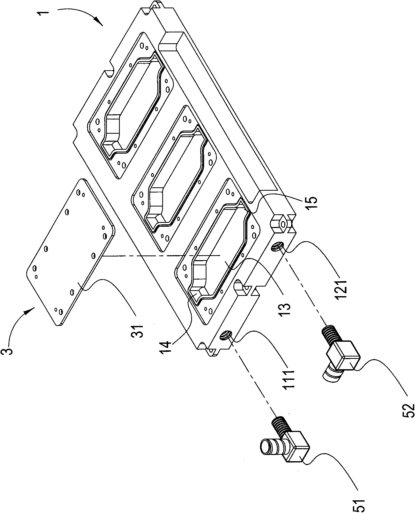
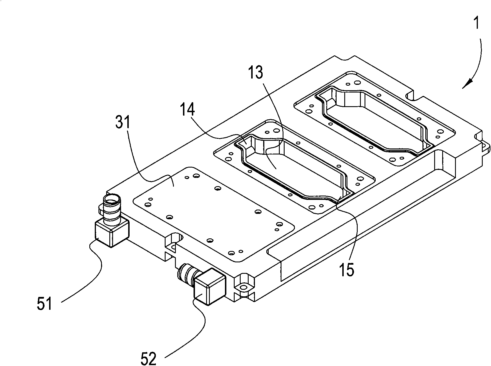
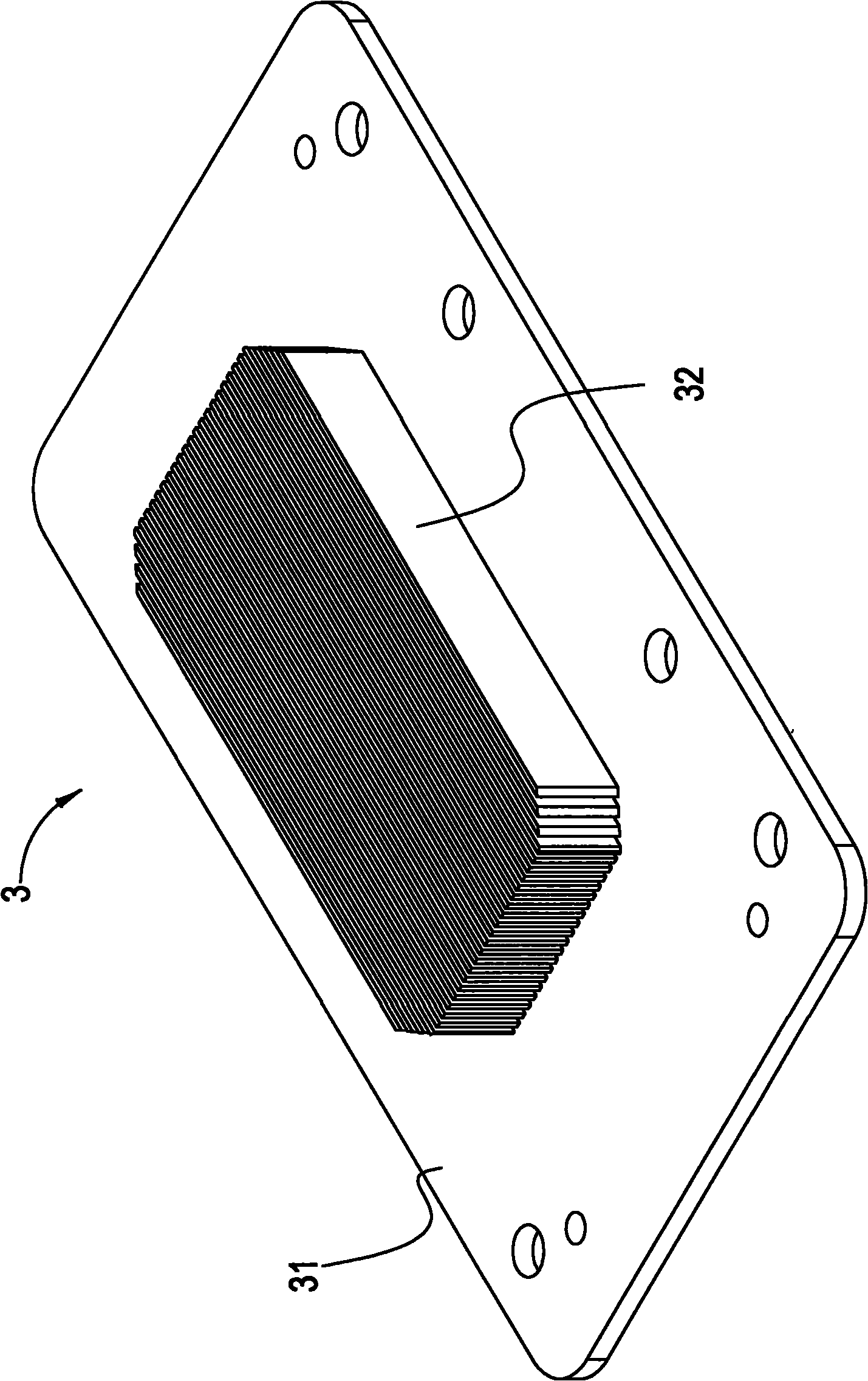
[0035] see figure 1 , figure 2 , Figure 3A , Figure 3B , Figure 4A , Figure 4B and Figure 4C , is the three-dimensional decomposition structure diagram, the three-dimensional combined structure diagram, the three-dimensional structure diagram of the heat dissipation fins, the top view of the heat dissipation fins and the schematic diagram of the liquid circulation heat dissipation of the liquid-cooled heat dissipation structure of the present invention. It can be seen from the figure that the liquid-cooled heat dissipation structure includes:
[0036] A base 1 has at least one liquid input pipeline 11, at least one liquid output pipeline 12 and at least one groove 13, and the inside of the groove 13 communicates with the liquid input pipeline 11 and ...
PUM
 Abstract
Description
Claims
Application Information