Engine device

An engine and exhaust gas purification device technology, applied in engine components, combustion engines, machines/engines, etc., can solve the problem of exhaust gas temperature drop in exhaust gas purification devices, and achieve the effect of improving versatility and preventing damage

Active Publication Date: 2011-08-17
YANMAR POWER TECHNOLOGY CO LTD
View PDF11 Cites 13 Cited by
  • Summary
  • Abstract
  • Description
  • Claims
  • Application Information

AI Technical Summary

Problems solved by technology

[0008] However, in the case of installing an exhaust gas purification device on a diesel engine, there is a problem that the engine vibration caused by driving is easily transmitted directly to the exhaust gas purification device. device, it is possible to reduce the temperature of the exhaust gas purification device and even the exhaust gas

Method used


Image

  • Engine device
  • Engine device
  • Engine device

Examples


Embodiment Construction

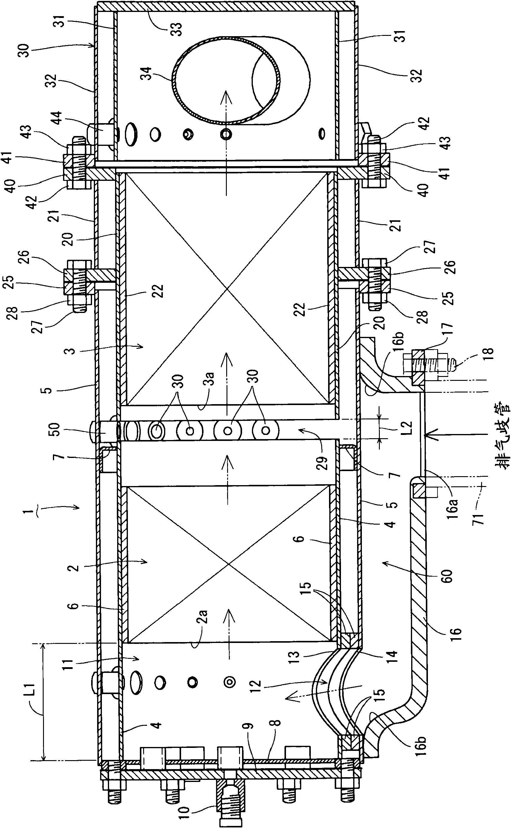
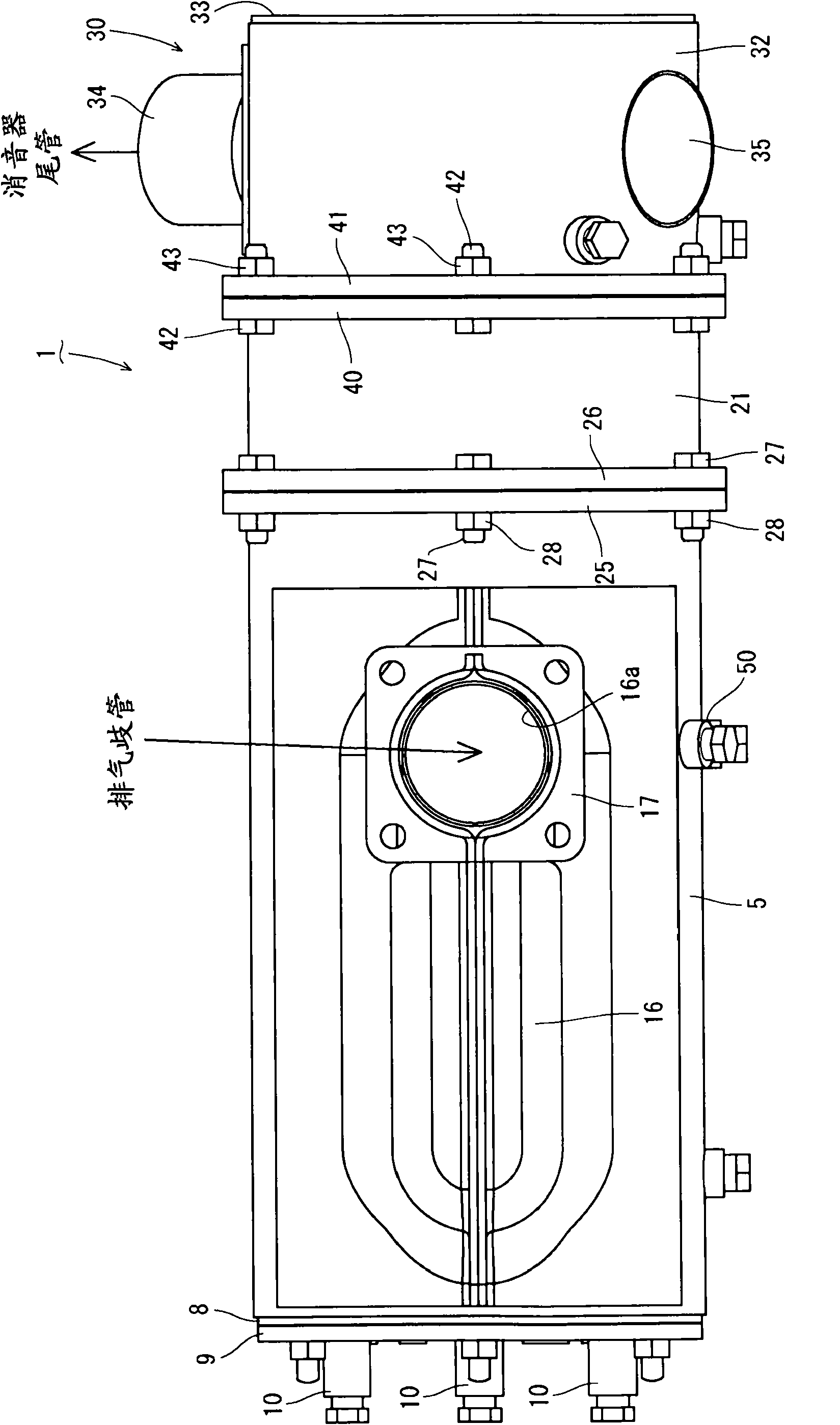
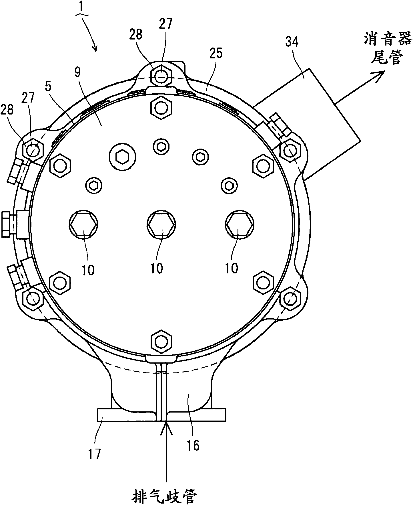
[0057] Hereinafter, embodiments embodying the present invention will be described based on the drawings. In addition, in the following description, the exhaust gas inlet 12 side of the diesel particulate filter 1 is referred to as the left side, and similarly, the muffler 30 side thereof is referred to as the right side.

[0058] First, refer to Figure 1 to Figure 5 The overall structure of the exhaust gas purification device of the first embodiment will be described. Such as Figure 1 to Figure 5 As shown, a continuous regeneration type diesel particulate filter 1 (hereinafter referred to as DPF) is provided as the exhaust gas purification device of the first embodiment. The DPF 1 is used to physically trap particulate matter (PM) and the like in exhaust gas. DPF1 is structured such that nitrogen dioxide (NO 2 ) platinum diesel oxidation catalyst 2, and a honeycomb structure soot filter 3 that continuously oxidizes and removes trapped particulate matter (PM) at relativel...


PUM


Abstract

An engine device in which a DPF (1), which is one of the components of an engine (70), is disposed in the engine (70) with high rigidity, which eliminates a measure against exhaust gas for each device of a vehicle, and which can improve the usability of the engine (70). The engine device comprises the engine (70) having an exhaust manifold (71) and the DPF (1) for purifying the exhaust gas exhausted from the engine (70). The cylinder head (72) of the engine (70) comprises filter support bodies (19a-19c) for supporting the DPF (1). The DPF (1) is connected to the exhaust manifold (71), and also connected to the cylinder head (2) with the filter support bodies (19a-19c) interposed therebetween.

Description

technical field [0001] The present invention relates to an engine device used in a work machine such as a backhoe, a forklift, or a tractor, and more specifically, relates to an attachment structure of an exhaust gas purification device to the engine. Background technique [0002] Conventionally, there are known technologies in which a diesel particulate filter (or NOx catalyst) or the like is provided as an exhaust gas purification device (aftertreatment device) in the exhaust path of a diesel engine, and a diesel particulate filter (or NOx catalyst) or the like is used , to purify the exhaust gas discharged from the diesel engine (see Patent Document 1, Patent Document 2, and Patent Document 3). Also, a technique of providing a filter case (inner case) in an outer case (outer case) and arranging a particulate filter in the filter case is also known (see Patent Document 4). [0003] Patent Document 1: Japanese Patent Laid-Open No. 2000-145430 [0004] Patent Document 2: J...

Claims


Application Information

Patent Timeline
Patent Type & Authority Applications(China)
IPC IPC(8): F01N3/24B01D53/94E02F9/00F01N3/28F02B67/00
CPCF01N2013/023F01N2590/08F01N13/1805F01N2013/026E02F9/0866F01N3/0335F01N13/1894Y02T10/20F01N2470/18E02F9/00F01N3/0211F01N13/1855F01N2470/02F01N13/0093F01N13/0097F02M35/10144F02M35/10288Y02T10/12B01D53/94F01N3/24F01N3/28
Inventor 光田匡孝小野寺恭志
Owner YANMAR POWER TECHNOLOGY CO LTD
Why Eureka
Try Eureka