Cooling system

A cooling system, coolant technology, used in liquid cooling, engine cooling, cooling/ventilation, etc., can solve problems such as damage, increase lubricating oil shear rate, increase tensile force, etc., to achieve effective operation and reduce warm-up time Effect

Active Publication Date: 2011-08-31
PROTEAN ELECTRIC LIMITED
View PDF4 Cites 10 Cited by
  • Summary
  • Abstract
  • Description
  • Claims
  • Application Information

AI Technical Summary

Problems solved by technology

For example, a steel crankshaft main bearing journal operating in an aluminum housing will have tighter clearances at lower temperatures, increasing the shear rate of the lubricating oil, which in

Method used


Image

  • Cooling system
  • Cooling system
  • Cooling system

Examples


Example Embodiment

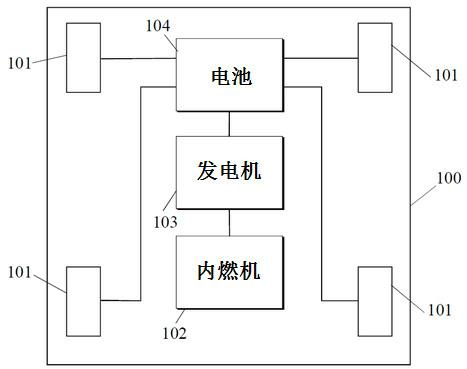
[0019] figure 1 A series hybrid vehicle 100 is shown having: a plurality of in-wheel electric motors 101, an internal combustion engine 102, a generator 103, and an energy storage device 104 such as a battery or capacitor.

[0020] The in-wheel electric motor 101 is configured to provide torque for driving the vehicle 100, as is well known to those skilled in the art. Typically, the in-wheel motor 101 may be integrated into at least two wheels (not shown) of the vehicle 100 . For example, in a car with four wheels, the in-wheel electric motors can be integrated into all four wheels or into both wheels, preferably on the same axle.

[0021] An example of an in-wheel electric motor is described in patent application GB 2 440 251.

[0022] Although the present embodiment describes a series hybrid vehicle having an in-wheel electric motor, it should be apparent to those skilled in the art that a series hybrid vehicle according to an embodiment of the present invention may also e...


PUM


Abstract

Disclosed is a cooling system for a vehicle having an engine and an electric motor, wherein the electric motor is arranged to generate a motor torque for driving the vehicle, the cooling system comprising means for transferring heat energy between the motor cooling means and the engine cooling means upon the occurrence of a predetermined criteria, wherein the motor cooling means is for controlling the temperature of the electric motor and the engine cooling means is for controlling the temperature of the engine.

Description

technical field [0001] The present invention relates to a cooling system, and more particularly to a cooling system for a vehicle having an engine and an electric motor configured to generate electric motor torque for driving the vehicle. Background technique [0002] A hybrid vehicle uses one or more electric motors to propel the vehicle, directly or indirectly using an internal combustion engine as a power source for the one or more electric motors. For example, hybrid internal combustion engines are employed in series, combined with electrical generators, to convert the chemical energy of hydrocarbon fuels into electrical energy, stored in a convenient form. [0003] Thus, for a series hybrid vehicle, the engine typically only needs to be started when the vehicle's electric motor needs to be charged, otherwise the engine does not need to utilize a significant amount of fuel. Thus, depending on the type of travel, the engine of a series hybrid vehicle may be started and s...

Claims


Application Information

Patent Timeline
IPC IPC(8): F01P3/18F01P7/16B60W10/06B60W10/08B60W20/00B60K6/46
CPCY02T10/642B60L2240/421H02K9/19F01P2025/46B60W2510/0676B60K1/02Y02T10/641Y02T10/6286Y02T10/54F01P2050/24F01P2005/105B60W2510/081F01P7/165B60L2260/167B60L2240/425B60K6/46H01M8/04029B60L2240/445B60W10/06F01P2025/08B60K2001/003Y02T10/6217F01P3/18B60W10/08B60W20/00Y02E60/50B60W2510/087B60K7/0007Y02T10/40Y02T10/62Y02T10/64B60K2006/268B60K11/02B60W10/30F01P3/02F01P7/14F02G5/00
Inventor 亚历山大·费舍尔
Owner PROTEAN ELECTRIC LIMITED
Why Eureka
Try Eureka