
Method and device for machining high-quality tiny through hole of hard and crisp material

A processing method and technology for hard and brittle materials, which are used in grinding devices, metal processing equipment, manufacturing tools, etc., can solve the problems of difficulty in guaranteeing the quality of the aperture edge, tool damage, angle error, etc., and achieve simple and feasible means and devices. High-quality surfaces and machining, the effect of high-efficiency machining

Inactive Publication Date: 2011-09-07
HARBIN INST OF TECH
View PDF5 Cites 21 Cited by
  • Summary
  • Abstract
  • Description
  • Claims
  • Application Information

AI Technical Summary

Problems solved by technology

[0002] With the development of micro-nano technology, more and more hard and brittle materials such as glass, ceramics and silicon wafers are used in the technical fields of microscope technology, near-field optical technology, micro-nano manufacturing and processing technology, jet processing technology and small hole measurement. In these technical fields, but for the processing of these hard and brittle materials micropores (less than 100 microns), no specific and effective solutions have been obtained.
The processing of micro-holes (less than 100 microns) in hard and brittle materials is a micro-processing technology for difficult-to-machine materials. The processing method for conductive materials is generally EDM, and the quality of the edge of the aperture is difficult to guarantee. Non-conductive materials generally use laser processing or conventional drilling. , boring and other processing methods, laser processing has aperture taper, edge heat-affected zone and burrs, although the current ultraviolet laser and femtosecond laser processing can obtain smaller apertures, but the processing efficiency is extremely low, while drilling, boring and other processing methods Often lead to tool damage and angle errors in holes and surfaces, resulting in workpiece damage

Method used


Image

  • Method and device for machining high-quality tiny through hole of hard and crisp material
  • Method and device for machining high-quality tiny through hole of hard and crisp material

Examples


Embodiment Construction

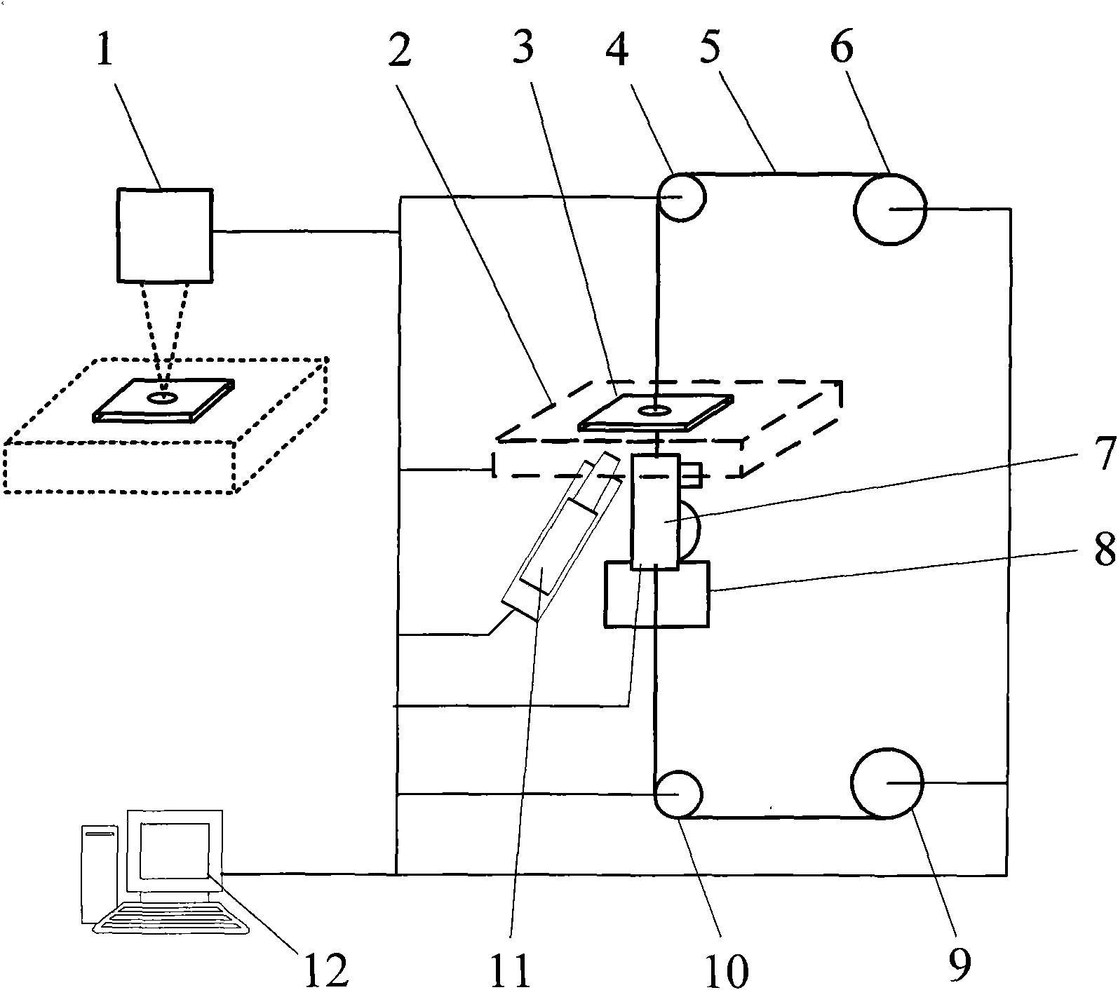
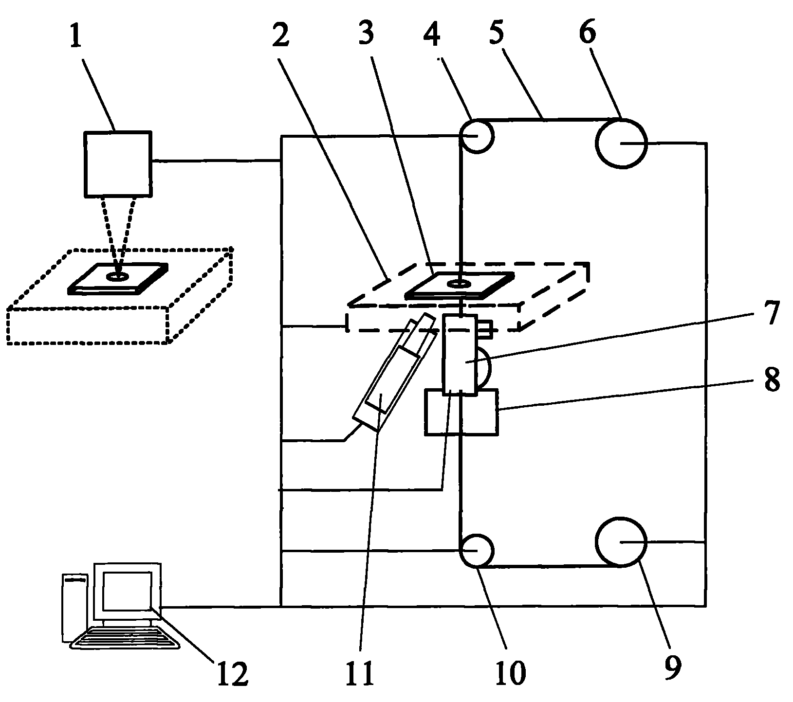
[0022] First, according to the material properties and processing technology of the workpiece 3, select the appropriate laser parameters to process the blank hole of the workpiece 3, and form a through hole on the workpiece. The aperture is slightly lower than the target diameter and larger than the diameter of the grinding wire 5, and then the workpiece 3 is installed. On the three-dimensional mobile clamping workbench 2 , estimate the position of the blank hole so that it is facing the grinding wire clamping guide wire device 7 under the three-dimensional mobile clamping workbench 2 .

[0023] The grinding wire 5 is wound on the rear wire disc 9, and the upper end of the grinding wire 5 is clamped into the grinding wire clamping wire guide device 7 through the rear guide wheel 10, and the clamping process is realized by the clamping knob of the grinding wire clamping wire guide device 7 , the degree of clamping needs to be controlled within a certain limit: the grinding wire ...


PUM

PropertyMeasurementUnit
Apertureaaaaaaaaaa

Abstract

The invention discloses a compound machining method which processes by aiming at the hard and crisp material micrometer-scale (less than 100 micrometers) apertures and causes the hard and crisp material to have high-quality aperture walls and edges. A blank hole is processed on an appointed position on a hard and crisp material to be processed by a specific laser beam; then, a special grinding wire penetrates into the blank hole to be ground; the grinding wire is controlled by an industrial personal computer to carry out longitudinal reciprocating motion, and the workbench of a clamping workpiece moves to realize machining operation; and during machining, the effect of a micropore is detected by an observation microscope until the obtained high-quality aperture walls and the edges can be obtained. The invention also provides a device for machining the high-quality tiny through hole of the hard and crisp material.

Description

technical field [0001] The invention belongs to the field of micro-hole processing of hard and brittle materials, and in particular relates to laser processing in unconventional manufacturing and other micro-through-hole processing methods, and a compound processing method and device with filament mechanical grinding. Background technique [0002] With the development of micro-nano technology, more and more hard and brittle materials such as glass, ceramics and silicon wafers are used in the technical fields of microscope technology, near-field optical technology, micro-nano manufacturing and processing technology, jet processing technology and small hole measurement. In these technical fields, however, no specific and effective solutions have been obtained for the processing of micropores (less than 100 microns) in these hard and brittle materials. The processing of micro-holes (less than 100 microns) in hard and brittle materials is a micro-processing technology for diffic...

Claims


Application Information

Patent Timeline
IPC IPC(8): B24B37/02
Inventor 杨立军王扬李春奇张宏志
Owner HARBIN INST OF TECH
Learn More