Mixing combustion guide coupling structure of combustion chamber

A coupling structure and combustion chamber technology, applied in the direction of combustion chamber, continuous combustion chamber, combustion method, etc., can solve the problems of increasing the length and weight of the engine, reducing the overall performance of the engine, and complex structure, so as to reduce pressure loss and increase thrust Ratio, the effect of improving cooling efficiency

Active Publication Date: 2011-09-07
BEIHANG UNIV
View PDF6 Cites 15 Cited by
  • Summary
  • Abstract
  • Description
  • Claims
  • Application Information

AI Technical Summary

Problems solved by technology

However, there are artificially defined boundaries between the various systems of traditional gas turbines. In order to meet the normal heating work of the conventional combustion chamber and ensure the combustion performance at the outlet of the combustion chamber, a guide has to be

Method used


Image

  • Mixing combustion guide coupling structure of combustion chamber
  • Mixing combustion guide coupling structure of combustion chamber
  • Mixing combustion guide coupling structure of combustion chamber

Examples


Embodiment Construction

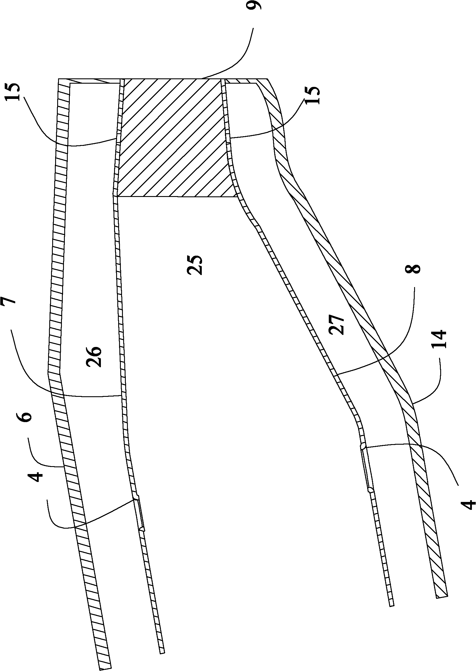
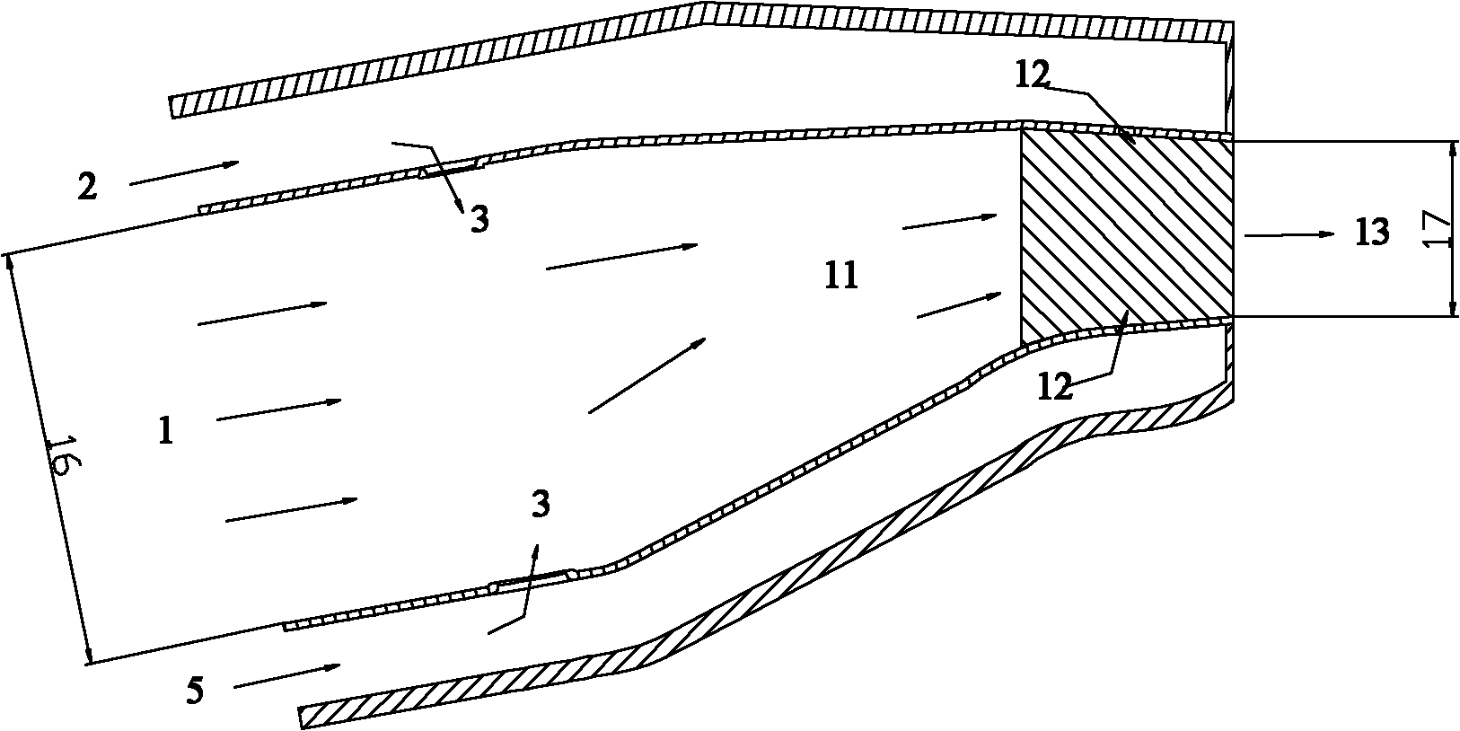
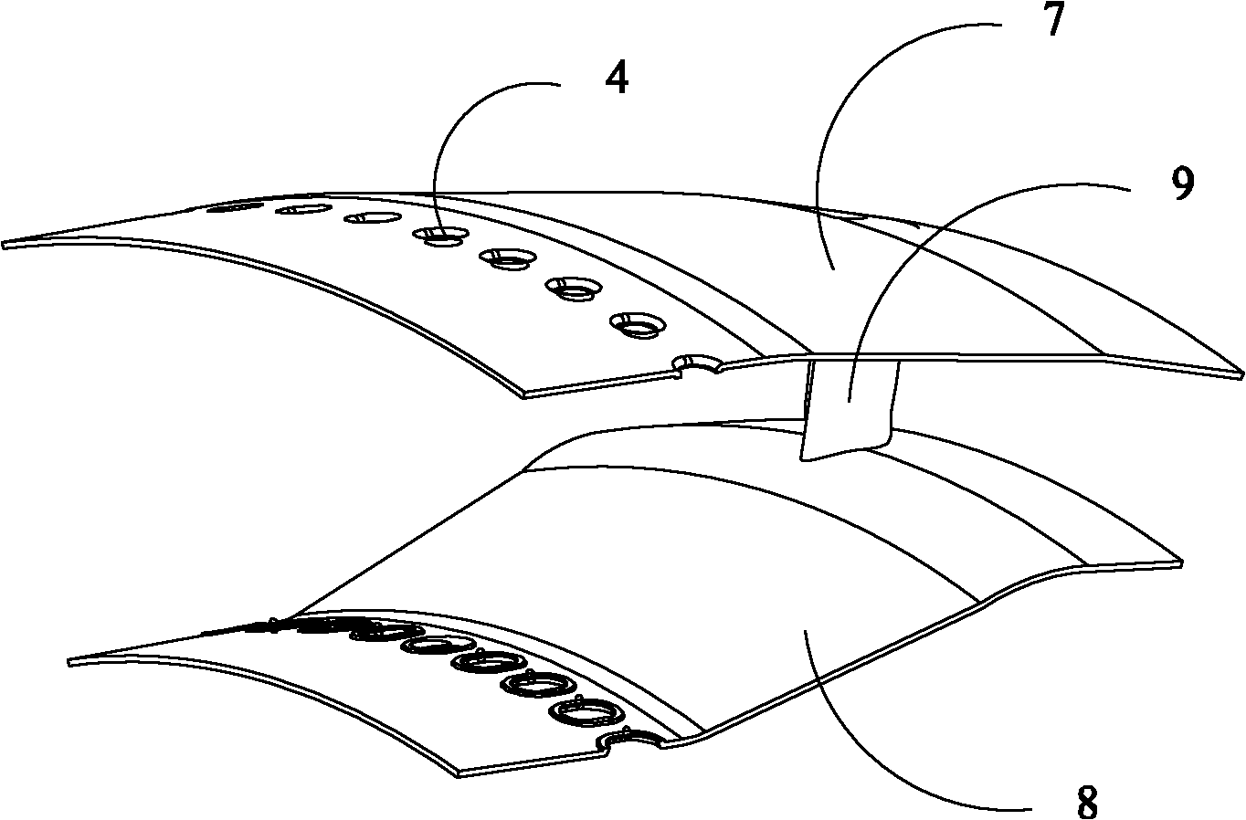
[0028] Such as figure 1 , 2 , shown in 3, the present invention is made of outer casing 6, inner casing 14, outer flame barrel 7, inner flame barrel 8 and turbine deflector vane 9, the outlet of outer flame barrel 7 and inner flame barrel 8 flame barrel is connected with machine The outlet of the box is fixedly connected.

[0029] Such as figure 1 , shown in 2, 3, and 4, the outer casing 6 and the inner casing 14, the inner flame cylinder 8 and the outer flame cylinder 7 are annular structures; The mixing hole 4 to the direction; the outer combustion chamber 26 is formed between the outer casing 6 and the outer flame cylinder 7, and the combustion inner annular chamber 27 is formed between the inner casing 14 and the inner flame cylinder 8; the turbine guide The blades 9 are evenly arranged in the shrinkage passage 25 between the outer flame tube 7 and the inner flame tube 8 along the circumferential direction, and the turbine guide blades 9 and the mixing holes 4 are at th...


PUM


Abstract

The invention discloses a mixing combustion guide coupling structure of a combustion chamber, which mainly comprises an outer receiver, an inner receiver, an outer flame tube, an inner flame tube and a turbine guider blade, wherein the turbine guider blade positioned at the downstream of mixing holes of the outer flame tube and the inner flame tube realizes coupling design of mixing, combusting, guiding and cooling, namely, mixing and combustion of mixing airflow and high-temperature fuel are realized, and temperature distribution of the outlet of the combustion chamber is regulated; guide diffusion of airflow at the outlet of the combustion is realized, tangential airflow conditions are provided for a high-pressure turbine moving blade; and mixing airflow facing to the turbine guider blade provides external cooling air for the turbine guider blade, therefore working environment of the turbine guider blade is improved and cooling effect is enhanced. Cooling air inside the turbine guider blade enters from an annular cavity of the combustion chamber, therefore structure design of a cooling air channel of a turbine guider is simplified and consumption of cooling air of the turbine guider is reduced.

Description

technical field [0001] The invention relates to a mixing and guiding coupling structure of a gas turbine full-circle combustion chamber, which is suitable for the mixing and combustion of the combustion chamber, the coupling of the guiding speed increase, meets the tangential airflow condition at the outlet, provides pre-swirl for the turbine drive, and realizes high-efficiency The cooling structure and cooling effect can simplify the structure, reduce the weight, and realize the compactness of the gas turbine. Background technique [0002] The basic performance and structural distribution of modern gas turbine combustors have reached a fairly high level, but there are still some problems and challenges for modern gas turbine combustors. The development and application of new materials, new processes, new structures, and new concepts is the key Guarantee its source of continuous improvement. [0003] A traditional gas turbine generally consists of an annular compression sys...

Claims


Application Information

Patent Timeline
IPC IPC(8): F23R3/16F23R3/52
Inventor 薛鑫林宇震许全宏张弛邹正平刘高恩
Owner BEIHANG UNIV
Why Eureka
Try Eureka