Optimization and design method for MRI (magnetic resonance imaging) superconducting magnet

A technology for magnetic resonance imaging and superconducting magnets, applied in superconducting magnets/coils, magnetic objects, applications, etc., which can solve the problem of difficulty in obtaining the global optimal result of the main magnet, decrease in magnet uniformity, and difficulty in obtaining the global optimal result, etc. question

Inactive Publication Date: 2011-09-07
INST OF HIGH ENERGY PHYSICS CHINESE ACADEMY OF SCI +1
View PDF4 Cites 20 Cited by
  • Summary
  • Abstract
  • Description
  • Claims
  • Application Information

AI Technical Summary

Problems solved by technology

The optimization algorithm here can be a simulated annealing algorithm or a genetic algorithm, which have a strong global optimization ability, but since the optimization problem of the MRI main magnet is a multi-parameter, multi-objective nonlinear programming problem, and it is necessary to predetermine the magnet’s The basic structure, so direct optimization of the structural parameters of the magnet has great blindness, and it is not easy to obtain the global optimal result
This method can find the optimal result of the magnet locally in the solution space, but it is still difficult to obtain the global optimal result of the main magnet
[0016] In the final stage of the above two methods, when actually winding the magnet, it is necessary to consider the cross-sectional size of the superconducting wire, discretize the coil size, and round the position and radius. After rounding and discretization, the uniformity of the magnet and other indicators usually have a significant decline, making the design results deviate from the optimal solution

Method used


Image

  • Optimization and design method for MRI (magnetic resonance imaging) superconducting magnet
  • Optimization and design method for MRI (magnetic resonance imaging) superconducting magnet
  • Optimization and design method for MRI (magnetic resonance imaging) superconducting magnet

Examples


Embodiment Construction

[0049] The present invention will be further described below in conjunction with the accompanying drawings and embodiments. Those skilled in the art should understand that the following descriptions are only for explaining the present invention, rather than limiting the protection scope of the present invention.

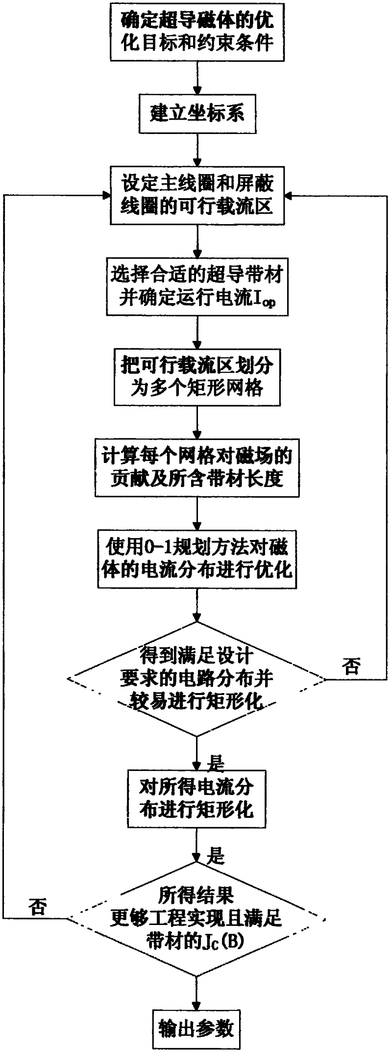
[0050] An optimal design method for a superconducting magnet for magnetic resonance imaging, the method is used to design a toroidal superconducting magnet including a main coil and a shielding coil structure, it goes without saying that this method is aimed at superconducting magnets with an active shielding structure Optimal design of magnets. Such as figure 1 shown, including the following specific steps:

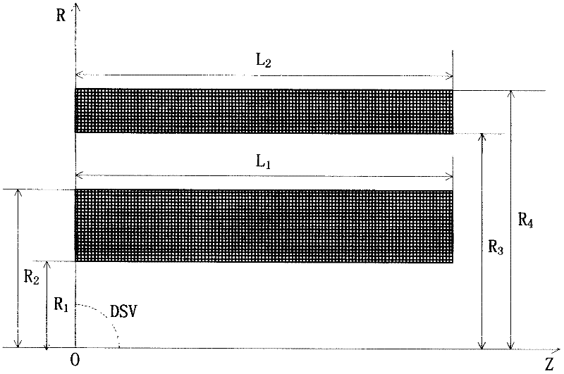
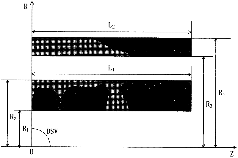
[0051] In step (1), a cylindrical coordinate system is established according to the requirements of the imaging area of ​​the superconducting magnet, and the z-axis of the cylindrical coordinate system coincides with the central axis of the superconducting mag...


PUM


Abstract

The invention discloses an optimization and design method for an MRI (magnetic resonance imaging) superconducting magnet, which is used for designing a solenoid-type superconducting magnet comprising a primary coil and a shielded coil. According to the cross section dimension of a superconducting tape, a feasible current-carrying zone is subjected to a rectangular net processing so that the axial size of each grid is equal to an integral multiple of the width of the superconducting tape and the radial size is equal to an even multiple of the thickness of the superconducting tape. The optimization and design method aims to minimize wire consumption under the constraint conditions of the central field strength, the magnetic field uniformity and the stray magnetic field of the superconducting magnet, the preliminary current distribution of the primary coil and the shielded coil can be obtained by a 0-1 programming algorithm; and different blocks of the superconducting magnet are subjected to rectangle formatting to obtain a final optimized result. By using the method, a globally optimal solution meeting design requirements can be obtained and the obtained design result is an integer turn, thus effectively avoiding round errors existing in a conventional method.

Description

technical field [0001] The invention belongs to the field of applied superconducting technology, and in particular relates to a method for optimizing the design of a spiral tube type superconducting magnet including a main coil and a shielding coil structure. Background technique [0002] Magnetic resonance imaging (MRI) is a high-tech imaging technology that utilizes the NMR properties of the magnetic nuclei (mainly hydrogen nuclei) of organisms in a magnetic field. Magnetic resonance imaging (MRI) equipment is mainly composed of a main magnet, a scanning bed, a gradient coil, a radio frequency coil, a spectrometer system, a control cabinet, a man-machine dialogue console, a computer, and an image processor. [0003] The main magnet is the main component of the MRI equipment, which is used to generate a uniform static magnetic field, which determines the image quality and work efficiency of the MRI equipment. At the same time, the main magnet is also the part with the larg...

Claims


Application Information

Patent Timeline
IPC IPC(8): H01F6/00G01R33/3815A61B5/055
Inventor 杜晓纪朱自安张国庆赵玲王美芬马文彬姚卫超侯治龙宁飞鹏王兆连李培勇胡金刚
Owner INST OF HIGH ENERGY PHYSICS CHINESE ACADEMY OF SCI
Why Eureka
Try Eureka