Method and device for removing dust in flue gas

A flue gas and dust technology, applied in the field of electrostatic dust removal methods and devices, can solve the problems of low removal rate of fine particles, failure to charge, and low collection efficiency, so as to enhance charging and collection performance, and reduce vibration secondary The effect of non-flying and good dust adaptability

Inactive Publication Date: 2011-09-14
TSINGHUA UNIV
View PDF4 Cites 18 Cited by
  • Summary
  • Abstract
  • Description
  • Claims
  • Application Information

AI Technical Summary

Problems solved by technology

At present, the commonly used high-efficiency dust removal devices mainly include electric dust removal devices and bag dust removal devices. Although the total dust removal efficiency of these dust removal devices can reach more than 99%, the removal rate of fine particles is relatively low. The average collection efficiency of the bag dust removal device for fine particles in the range of 0.1-1.0 μm is lower than 90%. Further research shows that a large part of the fine particles in the range of 0.03-0.2 μm will not be able to charge, but will be charged by adhesion. The coarse particles are removed together with the coarse particles, and the conventi

Method used


Image

  • Method and device for removing dust in flue gas
  • Method and device for removing dust in flue gas
  • Method and device for removing dust in flue gas

Examples


Embodiment Construction

[0019] Below in conjunction with accompanying drawing, structure of the present invention, principle and working process are further described:

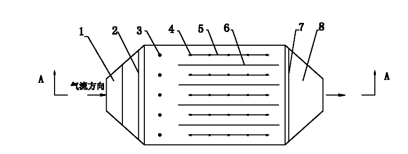
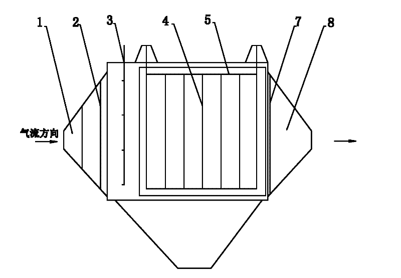
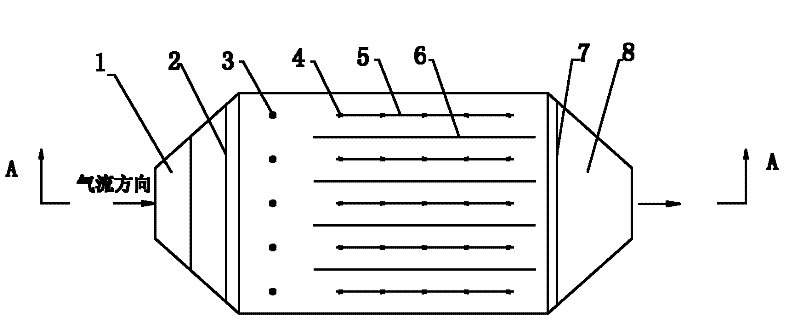
[0020] figure 1 and figure 2 The structure of the fume dedusting device provided by the present invention is shown. The dedusting device includes an intake fume box 1, an air distribution plate 2, an electrostatic atomizing nozzle 3, a dust collecting electric field, a grooved plate 7, an exhaust fume box 8 and Ash hopper, etc., the dust collecting electric field is provided with a pole line 4 and a dust collecting pole plate 6, the pole line is connected to the DC negative high voltage, and the dust collecting pole plate is grounded; among which the pole line can be RS barbed wire, spiral wire or a plate with weak discharge Shaped barbed wire, the dust collector plate can be a large C-shaped plate or a corrugated plate. At least one group of electrostatic atomizing nozzles is arranged between the air distribution plate and the du...


PUM

PropertyMeasurementUnit
Particle sizeaaaaaaaaaa

Abstract

The invention provides a method and device for removing dust in flue gas and relates to a static de-dusting method and device for collecting dust in industrial flue gas. By combining the principles of electrostatic spraying charge and electrostatic precipitation, an electrostatic spraying charge area is arranged between a gas-flow uniform distributing plate and a dust-collecting electric field. An electrostatic spraying method is used for loading negative charges on water droplets, wherein the dust and the charged water droplets mutually attract and collide and then flow by a dust-collecting electric field space; the dust-collecting electric field space comprises a polar line and a dust collecting polar plate; dust particles move towards the dust collecting polar plate and deposit on the dust collecting polar plate while the charged water droplets evaporate; and the collected dust falls into a dust bucket under the vibration action, thereby purifying the flue gas. The device comprises a gas-inlet smoke box, a gas-flow uniform distributing plate, a dust-collecting electric field, a slot plate, a gas-outlet smoke box and the dust bucket, and is technically characterized in that at least one group of electrostatic spraying nozzles are arranged between the gas-flow uniform distributing plate and the dust-collecting electric field. The device provided by the invention has the advantages of high de-dusting efficiency, especially higher de-dusting efficiency to the submicron-level dust and excellent dust adaptability, and can be used for reducing the secondary flying caused by the vibration of an electric de-dusting device.

Description

technical field [0001] The invention belongs to the technical field of flue gas dust removal, and in particular relates to an electrostatic dust removal method and device for collecting dust in industrial flue gas. Background technique [0002] The emission of particulate matter in the atmosphere, especially inhalable particulate matter (PM10) and finer particulate matter that can enter the lungs (PM2.5), has attracted widespread attention. In the body, the heavy metals and toxic and harmful substances rich in them can cause diseases of the respiratory system and cardiac system to worsen, and have carcinogenic, disabled and mutagenic effects, making the harm of fine particles to human health far greater than that of coarse particles. In addition, fine particles also have a huge impact on many environmental problems such as urban atmospheric visibility, acid deposition, photochemical smog, and the greenhouse effect. At present, the commonly used high-efficiency dedusting dev...

Claims


Application Information

Patent Timeline
IPC IPC(8): B01D50/00
Inventor 刘松涛卓建坤李水清宋蔷姚强
Owner TSINGHUA UNIV
Why Eureka
Try Eureka