Same end entrance-exit type continuous sputtering film plating device

A sputtering coating and equipment technology, applied in the field of the same-end in-out continuous sputtering coating equipment, can solve the problems of high operating cost, large area, huge equipment, etc. Small, high throughput effect

Active Publication Date: 2011-09-14
杭州比凡科电子科技有限公司
View PDF3 Cites 25 Cited by
  • Summary
  • Abstract
  • Description
  • Claims
  • Application Information

AI Technical Summary

Problems solved by technology

Most of the existing technologies use furnace-mounted vacuum evaporation coating, which has the disadvantages of poor bonding between the evaporated film and the substrate, poor uniformity and consistency of the film, low production efficiency, and easy introduction of human factors of operators.
China Patent No. 200610049197.3 discloses a continuous sputtering device, which consists of five vacuum chambers, including a pre-pumping chamber, a front transition chamber, a sputtering chamber, a rear transition chamber and a decompression chamber, as well as a film feeding table, a film discharging table, The workpiece rack return device and other components, the workpiece rack is transported out of the body through the film feeding table, pre-pumping chamber, front transition chamber, sputtering chamber, rear transition chamber and decompression chamber to the film output table, and then returned by the workpiece rack outside the body The device transports the workpiece rack back to the end of the film. The defect of this equipment is: because the workpiece rack enters from one end of the equipment and exits from the other end, there are many vacuum chambers, the equipment is huge, the cost is high, and the floor area is large; in order to prevent it from being polluted by dust, The production of electronic devices generally requires the workpiece holder and the entry and exit table to be carried out in an ultra-clean environment. Due to the large size of the equipment, it also has a very long return device for the external sheet holder, which requires a large volume and high operating costs. Ultra-clean room, therefore, the energy consumption of double-ended equipment is large, and the operating cost is expensive, which does not meet the requirements of the era of energy saving and emission reduction

Method used


Image

  • Same end entrance-exit type continuous sputtering film plating device
  • Same end entrance-exit type continuous sputtering film plating device
  • Same end entrance-exit type continuous sputtering film plating device

Examples


Embodiment

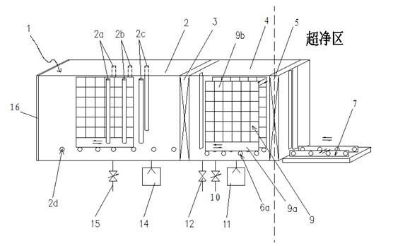
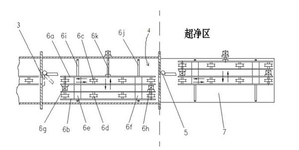
[0021] In the single-end continuous sputtering coating equipment of the present invention, a small ultra-clean table is arranged on one side of the loading and unloading table, and each workpiece rack can be loaded with a ceramic substrate of one square meter. Chromium-copper-silver coating takes about 5-6 minutes per machine, and the equipment occupies two-fifths less than the double-ended machine, the energy consumption is reduced by one-third, and the cost of the equipment is reduced 40%, and its annual throughput is almost the same as that of double-ended continuous sputtering equipment. To test the quality of the film, its uniformity, tensile strength, welding resistance and other indicators are the same as those of the double-ended machine.


PUM


Abstract

The invention relates to a same end entrance-exit type continuous sputtering film plating device, which comprises a vacuum cavity and a vacuum gas suction device, wherein the vacuum gas suction device is communicated with the vacuum cavity. The same end entrance-exit type continuous sputtering film plating device is characterized in that: the vacuum cavity consists of two vacuum chambers including a pre-suction chamber and a sputtering chamber which are adjacent to and communicated with each other; an isolating valve is arranged between the two vacuum chambers; the tail end and the front end of the cavity are provided with a blind flange and a vacuum lock valve respectively; the outer side of the vacuum lock valve is provided with a loading-unloading film board; a workpiece rest conveyor is arranged in the sputtering chamber; a composite conveyor is arranged in the pre-suction chamber; at least three pairs of relatively-arranged magnetron sputtering targets are arranged in the sputtering chamber; and the workpiece rest conveyor can be matched with a workpiece rest. The same end entrance-exit type continuous sputtering film plating device has the advantages of compact structure, small floor area, less required ultra-clean area, high throughput, low energy consumption, good film layer quality and the like.

Description

technical field [0001] The invention belongs to the technical field of sputtering coating, and in particular relates to a same-end in-out continuous sputtering coating device for electronic devices. Background technique [0002] Almost all electronic devices are coated with a metal film on one or more surfaces for subsequent processes such as electrode fabrication. Most of the existing technologies use furnace-mounted vacuum evaporation coating, which has the disadvantages of poor adhesion between the evaporated film and the substrate, poor uniformity and consistency of the film, low production efficiency, and easy introduction of the human factor of the operator. . Chinese Patent No. 200610049197.3 discloses a continuous sputtering equipment, which consists of five vacuum chambers, a pre-pumping chamber, a front transition chamber, a sputtering chamber, a rear transition chamber and a decompression chamber, as well as a wafer feeding stage, a wafer ejecting stage, The wor...

Claims


Application Information

Patent Timeline
Patent Type & Authority Applications(China)
IPC IPC(8): C23C14/34C23C14/56
Inventor 王德苗金浩顾为民任高潮沈小虎冯斌周剑
Owner 杭州比凡科电子科技有限公司
Why Eureka
Try Eureka