
Composite armored thermal insulation wall of foamed concrete and construction method thereof

A foam concrete and thermal insulation wall technology, applied in the direction of thermal insulation, walls, building components, etc., can solve the problems of low service life, small stress points of concrete slabs, low compressive strength of external walls, etc., and achieve compression resistance Strong ability, convenient construction and superior performance

Inactive Publication Date: 2011-09-14
LUOYANG NORMAL UNIV
View PDF8 Cites 13 Cited by
  • Summary
  • Abstract
  • Description
  • Claims
  • Application Information

AI Technical Summary

Problems solved by technology

Among them, the first three kinds of walls all have different degrees of shortcomings. The overall volume of the wall is large, the compressive strength of the outer wall surface is low, and the service life is low, which cannot be consistent with the service life of the building itself.
In the event of a fire, a large amount of toxic substances and black smoke will be produced, making it easy for people to inhale the smoke and difficult to escape, damaging the environment and may permanently endanger human health and pollute the environment
Foam concrete is integrally poured into the external wall. Although the total bulk density of the wall is reduced and there is no secondary pollution, there are problems such as easy cracking and water absorption, which reduces the thermal insulation performance and the whitewashing mortar is easy to fall off.
Chinese patent application No. 201010543013.5 discloses an ultra-light, ultra-strong and low-heat-transfer concrete composite bionic wall technology, which has high production costs, difficult construction, and small stress points on concrete slabs

Method used


Image

  • Composite armored thermal insulation wall of foamed concrete and construction method thereof
  • Composite armored thermal insulation wall of foamed concrete and construction method thereof
  • Composite armored thermal insulation wall of foamed concrete and construction method thereof

Examples


Embodiment 1

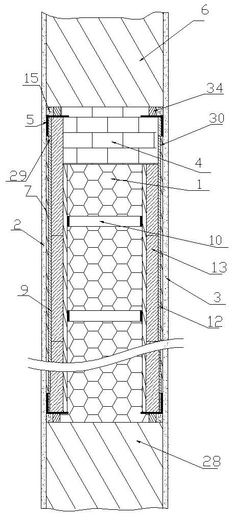
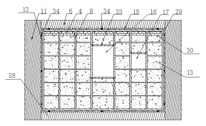
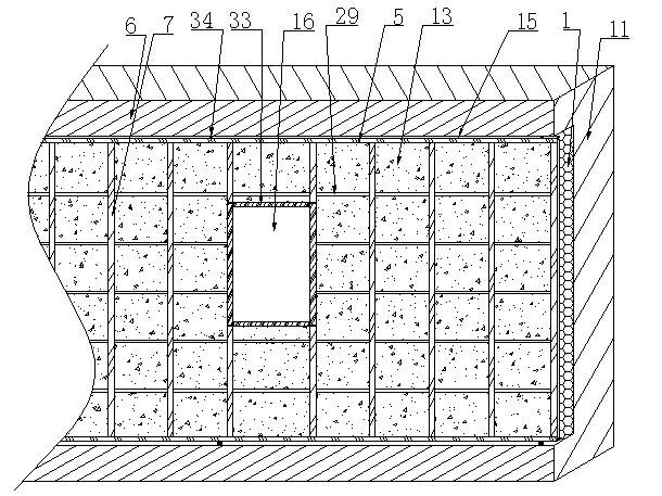
[0088] A construction method for a foam concrete composite armored thermal insulation wall, in which a window and a water and electricity control cabinet are arranged on the wall, and when the load-bearing column 11 and the upper and lower ring beams are provided with a reserved steel bar head 34, the method steps are as follows:

[0089] Step 1, the load-bearing column 11, the upper ring beam 6 and the lower ring beam 28 of the building are respectively set, and the distance between the outer surface of the upper ring beam 6 and the lower ring beam 28 and the outer surface of the load-bearing column 11 is 50mm;

[0090] Step 2. On the opposite sides of the two load-bearing columns 11, weld a vertical angle steel along the inner edge, respectively weld a horizontal angle steel on the lower end surface of the upper ring beam 6 and the upper end surface of the lower ring beam 28, and place the load-bearing column 11 The angle steel on the top and the angle steel on the upper and ...

Embodiment 2

[0106] A construction method of a foam concrete composite armored thermal insulation wall, when a door is provided on the wall, and a reserved steel bar head 34 is provided on the load-bearing column 11 and the upper and lower ring beams, the method steps are:

[0107] Step 1, the load-bearing column 11, the upper ring beam 6 and the lower ring beam 28 of the building are respectively set, and the distance between the outer surface of the upper ring beam 6 and the lower ring beam 28 and the outer surface of the load-bearing column 11 is 80mm;

[0108] Step 2. On the opposite sides of the two load-bearing columns 11, weld a vertical angle steel along the inner edge, respectively weld a horizontal angle steel on the lower end surface of the upper ring beam 6 and the upper end surface of the lower ring beam 28, and place the load-bearing column 11 The angle steel on the top and the angle steel on the upper and lower ring beams are welded to form a fixed frame 14; in the fixed fram...

Embodiment 3

[0125] A construction method for a foam concrete composite armored thermal insulation wall. When there are no windows, doorways, and water and electricity control cabinets on the wall, and there are no reserved steel bar heads 34 on the load-bearing columns 11 and the upper and lower ring beams, then it is necessary to install them on the load-bearing columns. 11 and the upper and lower ring beams are used to fix the load-bearing column angle steel 26, the angle steel 5 on the outer wall layer 9 and the fixed frame 14. Install expansion bolts to replace the reserved steel head 34. When installing the expansion bolts, drill holes first 1. Grouting cement mortar, then inserting expansion bolts, fastening, and then installing the inner wall panel layer 12 and the outer wall panel layer 9, the method steps are:

[0126] Step 1, the load-bearing column 11, the upper ring beam 6 and the lower ring beam 28 of the building are respectively set, and the distance between the outer surfac...


PUM

PropertyMeasurementUnit
thicknessaaaaaaaaaa
densityaaaaaaaaaa
densityaaaaaaaaaa

Abstract

The invention relates to a composite armored thermal insulation wall of foamed concrete and a construction method thereof, belonging to the field of thermal insulation walls, and the composite armored thermal insulation wall is used for a non-bearing wall of a building. The wall disclosed by the invention comprises an external wall plate layer, an internal wall plate layer, a foamed concrete insulating layer, a trowel finish mortar layer for an external wall surface, a trowel finish mortar layer for an internal wall surface, and foamed concrete filling blocks, wherein the foamed concrete insulating layer is arranged among the internal wall plate layer, a load bearing pillar and the external wall plate layer; the trowel finish mortar layer for the external wall surface and the trowel finish mortar layer for the internal wall surface are arranged on the external surfaces of the external wall plate layer and the internal wall plate layer; and the weight by volume of the foamed concrete of the wall disclosed by the invention is 200 to 400 kg / m<3>. The invention provides the novel thermal insulation wall which has the advantages of low manufacturing cost, convenience and rapidity for construction, light dead weight but high strength, prominent energy-saving effect, superior service performance and no secondary pollution.

Description

technical field [0001] The invention relates to a thermal insulation wall, in particular to a foam concrete composite armor thermal insulation wall with light weight, high strength and low heat transfer and a construction method. Background technique [0002] Energy conservation, pollution reduction and realization of low-carbon economy are the basic national policies of our country, among which building energy conservation is a very important aspect. Building energy saving is also the key to exterior wall and roof insulation. However, the exterior wall insulation technologies that are being used or promoted in my country include: ①External application of foam plastic boards; ②Use foam plastic boards as exterior wall sandwiches; Slurry made of microbeads and cement is applied to the outer wall; ④The bulk density is (700~1200)kg / m 3 Foam concrete integrally casts the exterior wall. Among them, the first three types of walls all have disadvantages in different degrees, such a...

Claims


Application Information

Patent Timeline
Patent Type & Authority Applications(China)
IPC IPC(8): E04B2/56E04B1/76E04G21/00
CPCE04B2002/8676E04B2/8652E04B2/88Y02A30/00Y02B30/90
Inventor 王利亚刘献明王建平李森兰
Owner LUOYANG NORMAL UNIV
Learn More