
Dimethyl ether engine fuel supply system and fuel injector thereof

A technology of dimethyl ether and fuel injectors, which is applied in the field of engines and can solve problems such as wear, engine power drop, and leakage

Inactive Publication Date: 2011-09-14
WEICHAI POWER CO LTD
View PDF6 Cites 3 Cited by
  • Summary
  • Abstract
  • Description
  • Claims
  • Application Information

AI Technical Summary

Problems solved by technology

[0005] However, the diesel engine will experience a power drop problem after burning dimethyl ether. The fuel injection frequency of the fuel injector is related to the engine speed, so the fuel injection frequency of the fuel injector is relatively high. It can be seen from the above that the needle valve and fuel injection The nozzle head needs to be contacted and separated at a high frequency. Due to the low viscosity of dimethyl ether, the wear of the needle valve and the nozzle head is relatively serious, and because dimethyl ether has no C-C bond, high-temperature cracking does not produce graphite If the buffer and anti-friction substances are used, the wear problem of the needle valve and the injector head will be more serious. Even if the lubricating additive is added to the dimethyl ether, the wear problem of the injector needle valve and the injector head will still occur. , which further leads to poor sealing of the fuel injector, fuel leakage, and reduced engine power
[0006] Therefore, how to reduce the wear of the needle valve and the head of the fuel injector in the fuel injector, avoid tight sealing, fuel leakage, and improve the power of the engine are technical problems that those skilled in the art need to solve

Method used


Image

  • Dimethyl ether engine fuel supply system and fuel injector thereof
  • Dimethyl ether engine fuel supply system and fuel injector thereof
  • Dimethyl ether engine fuel supply system and fuel injector thereof

Examples


Embodiment Construction

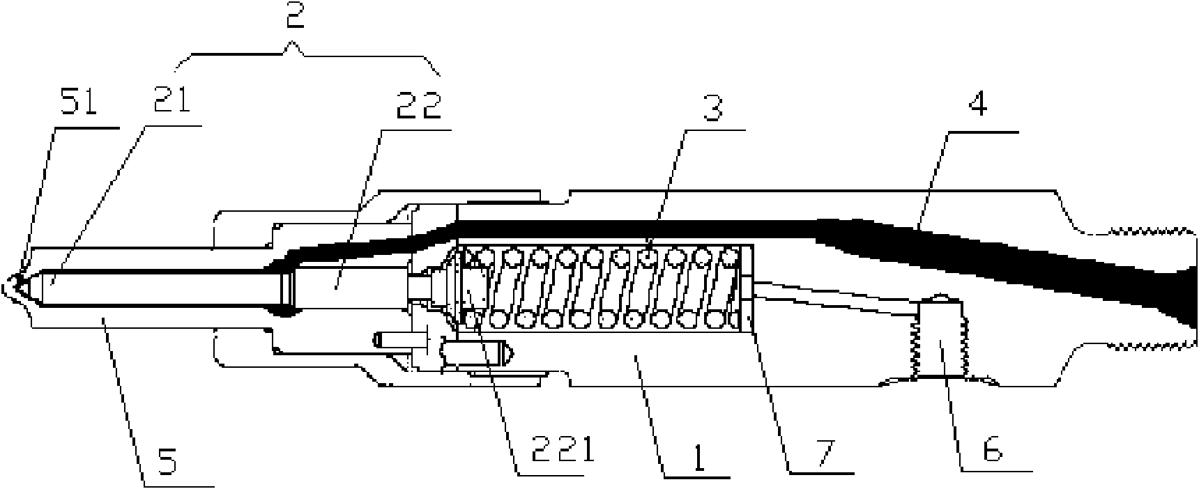
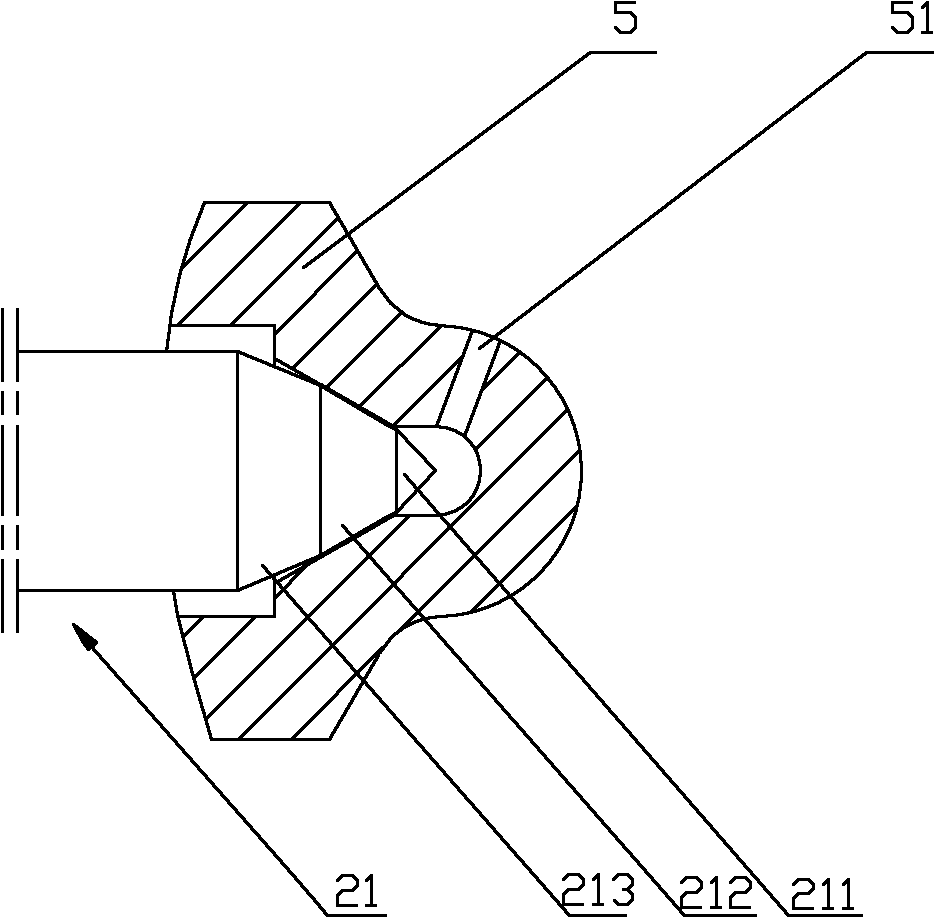
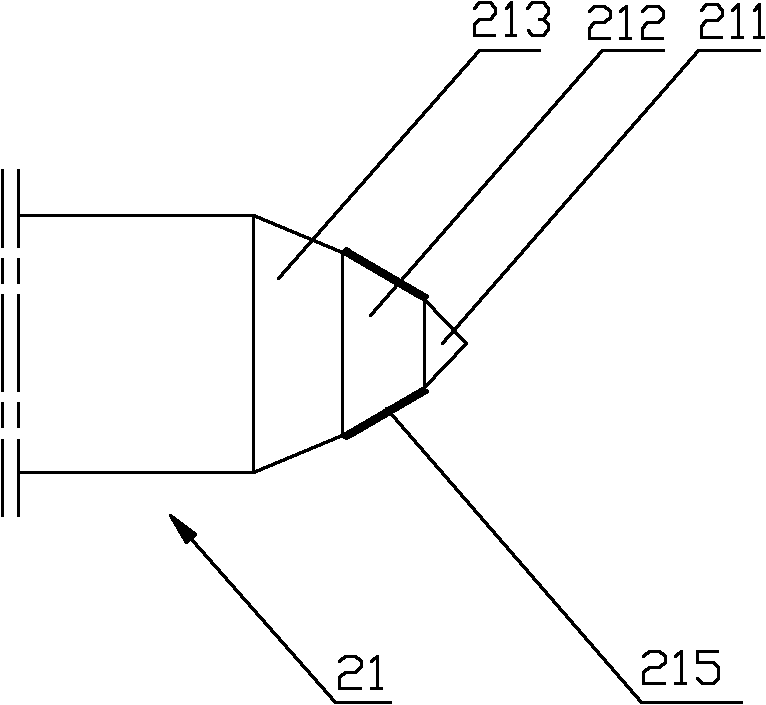
[0024] A core of the present invention is to provide a dimethyl ether injector, the needle valve of the injector and the contact surface of the injector have a wear-resistant coating, which can reduce wear, increase the service life of the injector, and avoid In order to prevent the tight sealing and fuel leakage, the power of the engine is improved. Another core of the present invention is to provide a DME engine fuel supply system comprising the above-mentioned DME injector.

[0025] In order to enable those skilled in the art to better understand the technical solutions of the present invention, the present invention will be further described in detail below in conjunction with the accompanying drawings and specific embodiments.

[0026] Please refer to figure 1 , figure 1 It is a structural schematic diagram of a specific embodiment of the dimethyl ether injector provided by the present invention; figure 2 for figure 1 Schematic diagram of the structure of the coopera...


PUM


Abstract

The invention discloses a dimethyl ether fuel injector. The dimethyl ether fuel injector comprises a needle valve body and a needle valve, wherein the needle valve body is provided with a fuel inlet channel communicated with a valve cavity of the needle valve body; a pressure regulation spring is arranged in the valve cavity of the needle valve body; a fuel nozzle is arranged on the head of the needle valve body; the fuel nozzle is provided with a fuel injection hole which is opened or closed by moving from the needle valve along the axial direction of the valve cavity; the surface, contacted with the inner cavity of the fuel nozzle, of the head of the needle valve is provided with an anti-abrasion coating layer. In the fuel injector, the anti-abrasion coating layer bears friction caused by a relevant reciprocating motion between the needle valve and the fuel nozzle, so that abrasion between the fuel nozzle of the oil injector and the needle valve can be reduced effectively, and the service life of the fuel injector is prolonged. The invention also provides a dimethyl ether engine fuel supply system comprising the fuel injector.

Description

technical field [0001] The invention relates to the technical field of engines, in particular to a dimethyl ether injector. The present invention also relates to a dimethyl ether engine fuel supply system comprising the above dimethyl ether injector. Background technique [0002] DME has the characteristics of low boiling point, low volumetric calorific value and low viscosity. Compression ignition combustion under high compression ratio has the same thermal efficiency as diesel engine. At the same time, the molecular formula of DME does not contain C-C bond, which can realize smokeless combustion. , therefore, dimethyl ether as a fuel for compression ignition engines can achieve clean combustion and is an excellent green energy source. [0003] The DME engine fuel supply system usually consists of a fuel tank storing DME fuel, a booster pump, a high-pressure pump, and an injector. When working, the booster pump obtains dimethyl ether fuel from the fuel tank, pressurizes i...

Claims


Application Information

Patent Timeline
IPC IPC(8): F02M61/10F02M61/18
Inventor 佟德辉冀丽琴孙少军张纪元
Owner WEICHAI POWER CO LTD
Learn More