
Microwave oven with light wind hydrogen new energy system serving as power supply source

A microwave oven, a new energy technology, applied in the field of microwave ovens

Inactive Publication Date: 2011-09-14
WUXI TONGCHUN NEW ENERGY TECH
View PDF3 Cites 4 Cited by
  • Summary
  • Abstract
  • Description
  • Claims
  • Application Information

AI Technical Summary

Problems solved by technology

This patent application is aimed at the microwave ovens used by millions of households, all of which rely on the power supply network to provide electricity. At present, 81% of the electricity in the power supply network comes from burning coal for power generation. If more electricity is consumed from the current power supply network, the increase in carbon dioxide emissions high emissions

Method used


Image

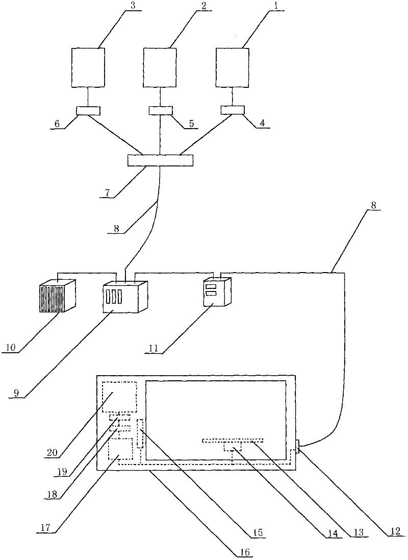
  • Microwave oven with light wind hydrogen new energy system serving as power supply source
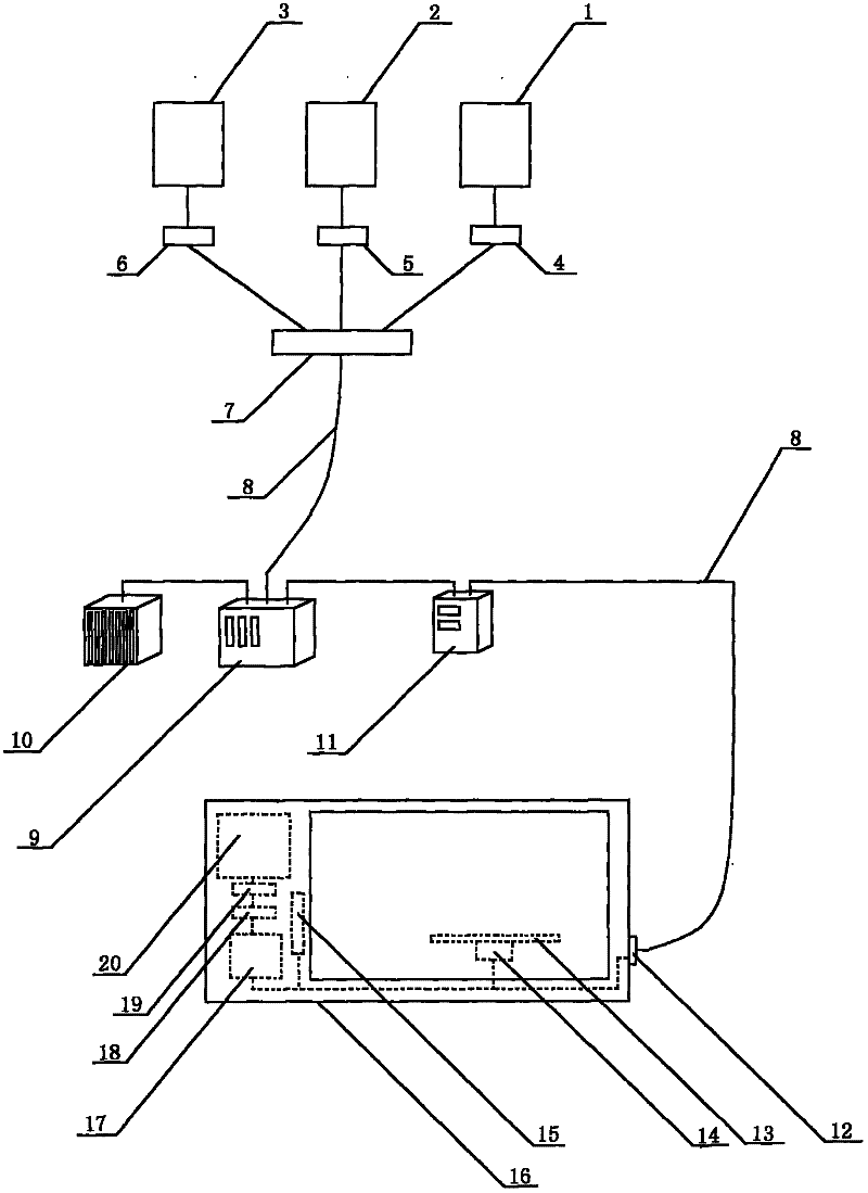
  • Microwave oven with light wind hydrogen new energy system serving as power supply source

Examples


Embodiment 1

[0017] The photovoltaic power generation system 1 is connected to the diode one 4 through the conductive wire 8, and the diode one 4 is connected to the power conversion combiner 7 through the conductive wire 8; the wind power generation system 2 is connected to the diode two 5 through the conductive wire 8 and the diode two 5 through the conductive wire 8. It is connected to the power conversion combiner 7; the proton exchange membrane hydrogen fuel cell 3 is connected to the diode three 6 through the conductive wire 8, and the diode three 6 is connected to the power conversion combiner 7 through the conductive wire 8; The controller 9 is connected, the controller 9 is connected to the energy storage battery 10 through a conductive wire 8, the controller 9 is connected to the inverter 11 through another conductive wire 8, and the inverter 11 is connected to the switch of the microwave oven through the conductive wire 8 12Connect.

Embodiment 2

[0019] The photovoltaic power generation system 1 is connected to the diode one 4 through the conductive wire 8, and the diode one 4 is connected to the power conversion combiner 7 through the conductive wire 8; the wind power generation system 2 is connected to the diode two 5 through the conductive wire 8 and the diode two 5 through the conductive wire 8. Connected to the power conversion combiner 7; the hydrogen phosphate fuel cell 3 is connected to the diode three 6 through the conductive wire 8, and the diode three 6 is connected to the power conversion combiner 7 through the conductive wire 8; the power conversion combiner 7 is connected to the controller through the conductive wire 8 9 is connected, the controller 9 is connected to the energy storage battery 10 through a conductive wire 8, the controller 9 is connected to the inverter 11 through another conductive wire 8, and the inverter 11 is connected to the switch 12 of the microwave oven through a conductive wire 8 ....


PUM


Abstract

The invention relates to a microwave oven with a light wind hydrogen new energy system serving as a power supply source and belongs to the technical field of new energy application. A photovoltaic power generation system, a wind power generation system and a hydrogen fuel battery generate a current respectively in power generation process; the three currents are converged into the current with increased current amount by an electric lead, a diode and a power conversion current convergence device; after the current with the increased current amount is regulated by a controller, a direct current is converted into an alternating current by an inverter; the alternating current is input into the microwave oven by a switch; after input into a high-voltage transformer and boosted, a part of the alternating current is input into a magnetically controlled microwave tube by a high-voltage capacitor and a high-voltage diode to generate a micro wave, so the heat of foods placed in a glass rotary plate inside an oven cavity is increased; and the other part of the alternating current drives a wind exhaust fan to exhaust wind and simultaneously drives the glass rotary plate and the foods in the glass rotary plate to rotate together, so an effect of uniformly increasing the heat is achieved.

Description

Technical field [0001] The invention relates to a microwave oven using a light wind hydrogen new energy system as a power supply, and belongs to the technical field of new energy applications. Background technique [0002] In the second half of 2010, many cities in China increased their efforts to save energy and reduce emissions. There is a city in the south of the Yangtze River. In order to achieve the goal of restricting the use of electricity provided by burning coal for power generation and controlling carbon dioxide emissions, more than 100 industrial enterprises were restricted. For power supply, some companies, in order to complete their annual production tasks, have to buy diesel to generate electricity at a relatively high price in the market to meet the power demand of the companies in production. This has aggravated the tight situation of diesel supply in the market. This caused a “diesel shortage” in society. Freight cars waiting to be refueled in front of gas statio...

Claims


Application Information

Patent Timeline
Patent Type & Authority Applications(China)
IPC IPC(8): F24C7/02F24C7/08H02N6/00F03D9/00H02S10/10H02S10/12H02S10/20
CPCY02E10/72Y02E10/50Y02E70/30
Inventor 缪同春
Owner WUXI TONGCHUN NEW ENERGY TECH
Learn More