
Flicker-wavelength-shifting optical fiber and fast neutron conversion screen

A technology for converting screens and optical fibers, applied in cladding fibers, optical waveguides and light guides, and measuring with scintillation detectors, etc. Improve the efficiency and resolution of fast neutron detection, achieve commercial mass production, and mature the generation process

Inactive Publication Date: 2011-09-14
PEKING UNIV
View PDF1 Cites 7 Cited by
  • Summary
  • Abstract
  • Description
  • Claims
  • Application Information

AI Technical Summary

Problems solved by technology

However, due to the opaqueness of the inorganic scintillator itself, the effective thickness of the ordinary ZnS screen is thin and the detection efficiency is low.
Adding wave-shifting (domestic called fluorescence: the same below) optical fiber to the scintillation screen can greatly increase the effective thickness of the scintillation screen, but the increase in thickness also causes a decrease in resolution
On the other hand, fast neutron scintillation screens have no standard size and are not suitable for mass production with special equipment. It is difficult to evenly distribute wave-shifting fibers in the scintillation screen without special equipment, and designing special equipment will greatly increase the cost. Currently, there is no Proper process for making

Method used


Image

  • Flicker-wavelength-shifting optical fiber and fast neutron conversion screen
  • Flicker-wavelength-shifting optical fiber and fast neutron conversion screen
  • Flicker-wavelength-shifting optical fiber and fast neutron conversion screen

Examples


Embodiment Construction

[0028] The present invention will be described in further detail below in conjunction with the accompanying drawings.

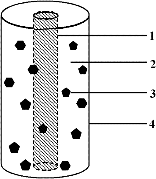
[0029] figure 1 It is a scintillation-wave-shifting optical fiber for fast neutron detection. The core layer 1 is a wave-shifting (fluorescent) optical fiber, the cladding layer is a high hydrogen-containing organic substance 2 doped with phosphor powder 3 , and the outermost layer is a reflective film 4 . According to the resolution requirements, the diameter of the wave-shifting (fluorescent) fiber in the core layer 1 is 1 / 4 to 3 / 4 of the total diameter of the flicker-wave-shifting fiber, generally 0.25 to 1 mm; The mass ratio of the phosphor powder 3 ranges from 1:1 to 9:1, or the mass doping ratio of the phosphor powder is 10% to 50%, generally 1:1; the coated outer reflective film 4 can be an aluminum film.

[0030] Fast neutron detection with scintillation - the diameter of the wave-shifting fiber determines the resolution of the fast neutron conversio...


PUM

PropertyMeasurementUnit
Lengthaaaaaaaaaa

Abstract

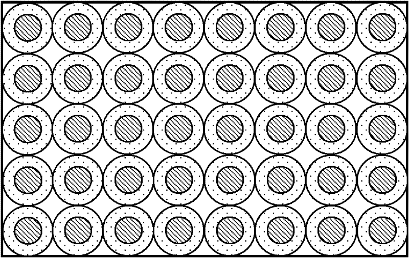
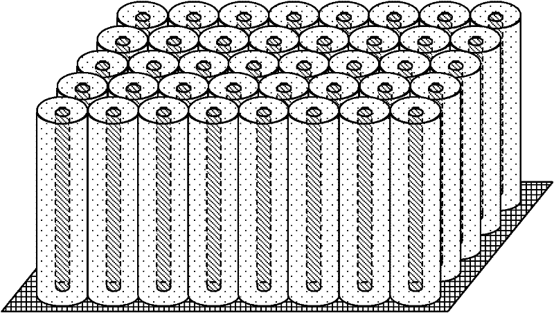
The invention discloses a flicker-wavelength-shifting optical fiber and a fast neutron conversion screen, belonging to the field of fast neutron imaging. The optical fiber disclosed by the invention sequentially comprises a core layer, a covering layer and a reflection film from inside to outside, wherein the core layer is a wavelength-shifting optical fiber, the covering layer is a hydrogen-containing organic matter doped with fluorescent powder, and the wavelength-shifting optical fiber of the core layer can absorb light emitted by the fluorescent powder of the covering layer and emit secondary photons. In the fast neutron conversion screen disclosed by the invention, a screen surface is formed by a plurality of sections of optical fiber end faces obtained by arraying optical fibers with equal lengths. Compared with the prior art, the invention ensures that the thickness of the conversion screen can be greatly improved, fast neutron detection efficiency can be increased by over 10 times compared with the common ZnS screen; and the reflection film on the outer layer can enhance the light-emitting strength of the conversion screen and effectively increase the resolution rate of the conversion screen. The invention has a matured generation process and can realize commercialized volume production.

Description

technical field [0001] The invention belongs to the field of fast neutron imaging, in particular to a scintillation-wave-shifting optical fiber for fast neutron imaging based on wave-shifting (fluorescence) optical fiber and a reflective film for high-performance fast neutron detection-wave-shifting optical fiber and based on scintillation-wave-shifting optical fiber Fabricated fast neutron transition screen. Background technique [0002] Neutron imaging is a new type of non-destructive detection technology. Since neutrons are not charged and have strong penetrability to matter, they can be used to measure the internal characteristics and information of objects or materials with large volumes and high densities. At the same time, neutrons have a large reaction cross-section with some light elements such as H, Li, and Be, which can make up for the gaps that are not easy to detect on these light elements by ordinary detection methods. At present, neutron imaging has been wid...

Claims


Application Information

Patent Timeline
IPC IPC(8): G02B6/02G01T3/06
Inventor 邹宇斌刘树全唐国有
Owner PEKING UNIV
Learn More