
Semiconductor packaging bonding process

A technology of semiconductor and chip bonding, which is applied in the manufacture of semiconductor/solid-state devices, electrical components, circuits, etc. It can solve the problems that the chip bonding process cannot meet the packaging requirements of small-volume packages, the production time of the chip bonding process is long, and products cannot be packaged. , to achieve the effects of controlling manufacturing costs, good flatness, and improving production efficiency

Inactive Publication Date: 2011-09-14
嘉盛半导体(苏州)有限公司
View PDF5 Cites 18 Cited by
  • Summary
  • Abstract
  • Description
  • Claims
  • Application Information

AI Technical Summary

Problems solved by technology

Due to the need to dispense glue one by one and absorb one by one, the production time of the existing chip bonding process is longer, the production efficiency is low, and the glue layer is uneven due to the glue dispensing process, which often causes chip unevenness
[0004] In addition, the existing semiconductor packaging technology is mostly used for conventional semiconductor packaging products with a packaging size of 3mm*4mm*1mm. The miniaturized package body of the product, because the product is extremely small, the adhesive glue required is also very thin, so the amount of glue dispensing must be strictly controlled to avoid the problem of glue overflow after the chip and the substrate are bonded, which is a problem for the existing packaging technology Regardless of material performance, machine precision, process parameter control, process stability and repeatability, the existing process technology has been unable to package such tiny products, and its die-bonding process has been unable to meet the needs of small-volume packaging. body packaging requirements

Method used


Image

  • Semiconductor packaging bonding process
  • Semiconductor packaging bonding process
  • Semiconductor packaging bonding process

Examples


Embodiment Construction

[0033] The following will clearly and completely describe the technical solutions in the embodiments of the present invention with reference to the accompanying drawings in the embodiments of the present invention. Obviously, the described embodiments are only some, not all, embodiments of the present invention. Based on the embodiments of the present invention, all other embodiments obtained by persons of ordinary skill in the art without creative efforts fall within the protection scope of the present invention.

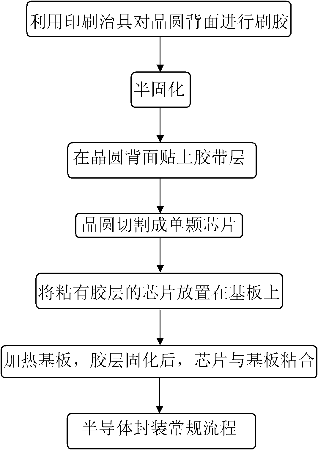
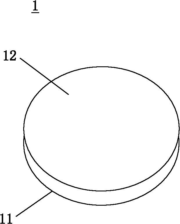
[0034] Such as Figure 2-9 As shown, the chip bonding process of the semiconductor package of the present invention comprises the following steps: a) Glue brushing: a wafer 1 is provided, which has a front side 11 and a back side 12, and the back side of the wafer 12 is a bare silicon surface. A layer of bonding glue 2 is coated on the round back 12; b) dicing: cutting the wafer 1 coated with bonding glue 2 to form a plurality of chips 13 separated from each other;...


PUM


Abstract

The invention discloses a semiconductor packaging bonding process comprising the following steps: a) carrying out adhesive coating: providing a wafer, wherein the wafer is provided with a front side and a back side, the back side of the wafer is a naked silicon side and coated with a layer of adhesive; b) cutting: cutting the wafer coated with the adhesive, so as to form a plurality of chips which are separated from one another; and c) bonding the surface, coated with the adhesive, of each separated chip with a base plate. For the semiconductor packaging bonding process, the back side of the whole wafer is directly coated with the adhesive layer, and then the wafer is cut into single chips, so that the time and labor for adhesive dispersing on the base plate can be saved, the process is simpler, the operability is strong and the production efficiency is greatly improved.

Description

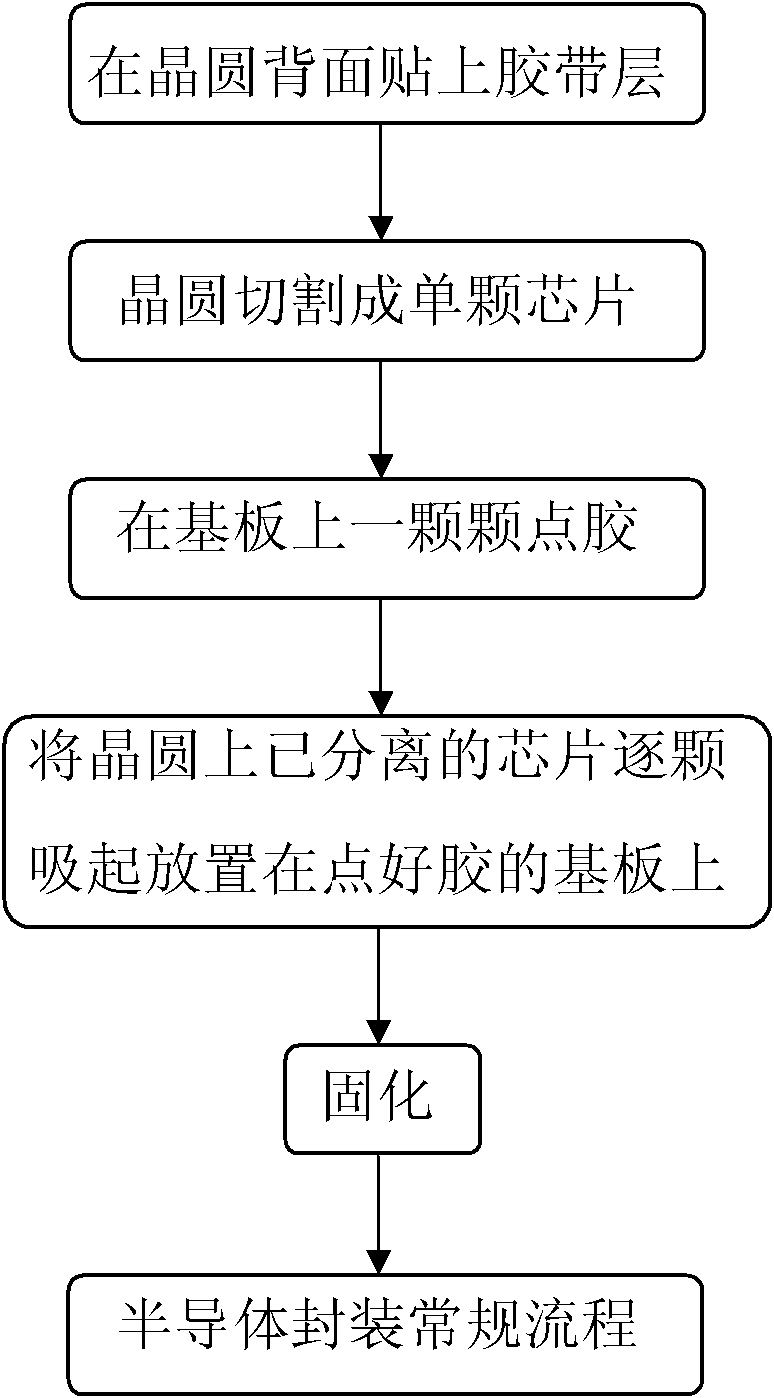
technical field [0001] The invention relates to a chip bonding process, in particular to a chip bonding process for semiconductor packaging. Background technique [0002] Semiconductor packaging refers to the process of processing the tested wafers according to the product model and functional requirements to obtain independent chips. Such as figure 1 As shown, the process steps of the existing semiconductor packaging process are: 1) paste the tape layer on the back of the wafer; 2) cut the large-size wafer into single chip units; 3) coat the rings one by one on the substrate Oxygen resin glue; 4) Place the cut chip units one by one on the glue-coated substrate; 5) Bond the chip and the substrate after baking; 6) Perform the conventional process of semiconductor packaging. The conventional process of semiconductor packaging includes: connecting the tiny pads on the chip with the designed pins on the substrate through wire bonding technology to complete the electrical inter...

Claims


Application Information

Patent Timeline
Patent Type & Authority Applications(China)
IPC IPC(8): H01L21/50H01L21/58
Inventor 王飞吴斌陈武伟
Owner 嘉盛半导体(苏州)有限公司
Learn More