Synchronous rectification driving circuit of flyback converter
A flyback converter and synchronous rectification technology, applied in the direction of DC power input conversion to DC power output, instruments, electrical components, etc., can solve problems affecting circuit efficiency or reliability, and achieve simple application, reliable shutdown, and circuit simple effect
- Summary
- Abstract
- Description
- Claims
- Application Information
AI Technical Summary
Problems solved by technology
Method used
Image

Examples
Embodiment Construction
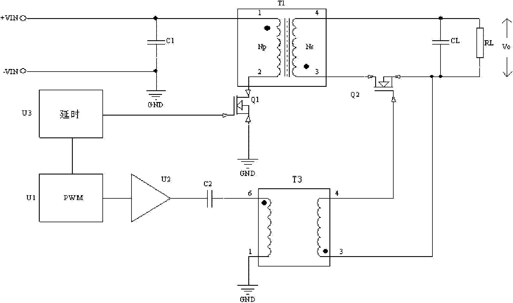
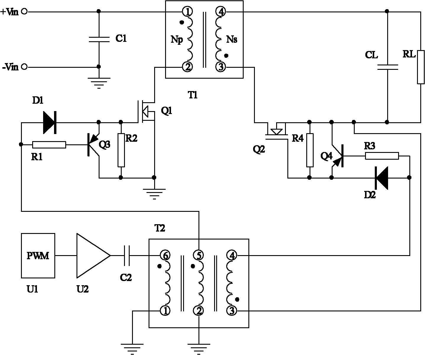
[0019] figure 2 It is a schematic circuit diagram of a flyback converter applying the best specific implementation mode of the synchronous rectification drive circuit of the present invention. The flyback converter includes an input part, a converter part, an output part, a driving circuit and a PWM chip U1. The input part, the converter part and the output part are prior art, and the drive circuit is the object to be protected by the present invention. The content to be protected by the present invention is not limited to the drive circuit applied to the converter described in this embodiment. The driving circuit can be applied to all flyback converters adopting synchronous rectification.
[0020] The input part includes a filter capacitor C1; the converter part includes a power transformer T1, a switch tube Q1 and a synchronous rectifier Q2; the output part includes an output capacitor CL; one end of the filter capacitor C1 is grounded, and the other end is connected to th...
PUM
 Abstract
Description
Claims
Application Information
 - Generate Ideas
- Intellectual Property
- Life Sciences
- Materials
- Tech Scout
- Unparalleled Data Quality
- Higher Quality Content
- 60% Fewer Hallucinations
Browse by: Latest US Patents, China's latest patents, Technical Efficacy Thesaurus, Application Domain, Technology Topic, Popular Technical Reports.
© 2025 PatSnap. All rights reserved.Legal|Privacy policy|Modern Slavery Act Transparency Statement|Sitemap|About US| Contact US: help@patsnap.com