Infrared receiver

An infrared receiver and comparator technology, applied in the field of infrared receivers, can solve problems such as short idle time, short remote control signal, and large circuit area, and achieve the effects of improving reliability, reducing cost, and improving applicability

Active Publication Date: 2014-09-10
QX MICRO DEVICES
View PDF4 Cites 0 Cited by
  • Summary
  • Abstract
  • Description
  • Claims
  • Application Information

AI Technical Summary

Problems solved by technology

[0006] The disadvantage of traditional technology is that: the strong modulation noise generated by electronic fluorescent lamps does not exceed 50% of the pulse input period, which is similar to normal signals and will be mistaken for normal signals, so that the infrared receiver will output this noise Signal
[0008] However, CN200410000199.4 "infrared receiver" also has disadvantages: the idle time of some normal remote control signals is also relatively short, which will be mistaken for noise signals, so that the infrared receiver cannot correctly output this remote control signal
[0009] The "infrared receiver" disclosed in CN200610162322.1 also cannot normally receive remote control signals with short idle time
[0010] CN201010146074.8 discloses "infrared receiver with mode conversion type gain control unit" although it can normally receive remote control signals with short idle time, but its circuit is relatively complicated and the circuit area is large

Method used


Image

  • Infrared receiver
  • Infrared receiver
  • Infrared receiver

Examples


Embodiment Construction

[0062] The present invention will be described in further detail below in conjunction with accompanying drawing:

[0063] Figure 1 to Figure 8 A first embodiment of the invention is shown.

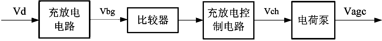
[0064] see figure 1 As shown, in this embodiment, the infrared receiver includes:

[0065] an input unit including a photodiode for converting an infrared input signal received from the outside into an electrical signal;

[0066] a preamplifier, amplifying the electrical signal converted by the input unit;

[0067] a variable gain amplifier, amplifying the electrical signal amplified by the preamplifier, and controlling the gain of the variable gain amplifier;

[0068] a limiting amplifier, amplifying the electrical signal amplified by the variable gain amplifier;

[0069] a bandpass filter for filtering out noise outside the passband in the electrical signal amplified by the limiting amplifier;

[0070] a comparator, comparing the signal output by the bandpass filter with a preset...


PUM


Abstract

The invention relates to an infrared receiver, which comprises an input unit, a preamplifier, a variable gain amplifier, a limiting amplifier, a band-pass filter, a comparator, a demodulator, an output unit and a gain control circuit, wherein the input unit is used for converting an infrared input signal received from the outside into an electric signal; the preamplifier is used for amplifying the electric signal; the variable gain amplifier is used for amplifying the electric signal and controlling gain; the limiting amplifier is used for amplifying the electric signal; the band-pass filter is used for filtering noise outside a pass band in the electric signal; the comparator is used for comparing the signal with a preset reference voltage; the demodulator is used for demodulating the signal; the output unit is used for receiving an envelope signal output by the demodulator, reshaping the waveform and outputting the envelop signal to the outside; and the gain control circuit is used for receiving a signal output by the demodulator, distinguishing noise and a normal signal, and generating corresponding gain control current or voltage for controlling the gain of the variable gain amplifier so as to filter the noise or amplify the normal signal.

Description

technical field [0001] The invention relates to an infrared receiver. Background technique [0002] An infrared receiver generally refers to a receiving device that receives infrared signals from an infrared data sending device and processes the received infrared signals. [0003] In addition to the normal remote control signal, the input signal received by the infrared receiver usually includes various noises generated by ambient light such as sunlight, incandescent and fluorescent lights, and these noises will degrade the performance of the infrared receiver. These noises must be filtered out for the IR receiver to work reliably. [0004] Figure 17 Shown is the circuit diagram of a traditional infrared receiver, including the input circuit of the photodiode to convert the external infrared signal into a weak electrical signal, which is amplified by the preamplifier; the variable gain amplifier amplifies the output signal of the preamplifier and can Gain control; the out...

Claims


Application Information

Patent Timeline
Patent Type & Authority Patents(China)
IPC IPC(8): H04B10/60G08C23/04
Inventor 毛晓峰李永红黄朝刚
Owner QX MICRO DEVICES
Why Eureka
Try Eureka