Biotype femoral head surface substitutive prosthesis

A femoral head, bio-based technology, applied in the direction of femoral head, prosthesis, joint implants, etc., can solve the problems of short prosthesis life, large resection surface, unequal walking, to avoid bone cement loosening, prosthesis life Long, strong bond effect

Inactive Publication Date: 2011-09-21
张前法
View PDF8 Cites 14 Cited by
  • Summary
  • Abstract
  • Description
  • Claims
  • Application Information

AI Technical Summary

Problems solved by technology

However, in the current femoral head surface replacement prosthesis surgery, the femoral neck needs to be resected. The resection surface of the femur is relatively large, and the femoral neck is basically missing, which changes the original biomechanical properties of the hip joint. The bone cement filled between the bone and the prosthesis is also loose due to long-term mechanical wear, resulting in weak bonding between the prosthesis and the femur, and the life of the prosthesis is short; for young and middle-aged patients, the femoral head prosthesis needs to be replaced many times. body, which causes multiple surgical pains and economic burdens

Method used


Image

  • Biotype femoral head surface substitutive prosthesis
  • Biotype femoral head surface substitutive prosthesis
  • Biotype femoral head surface substitutive prosthesis

Examples


Embodiment 1

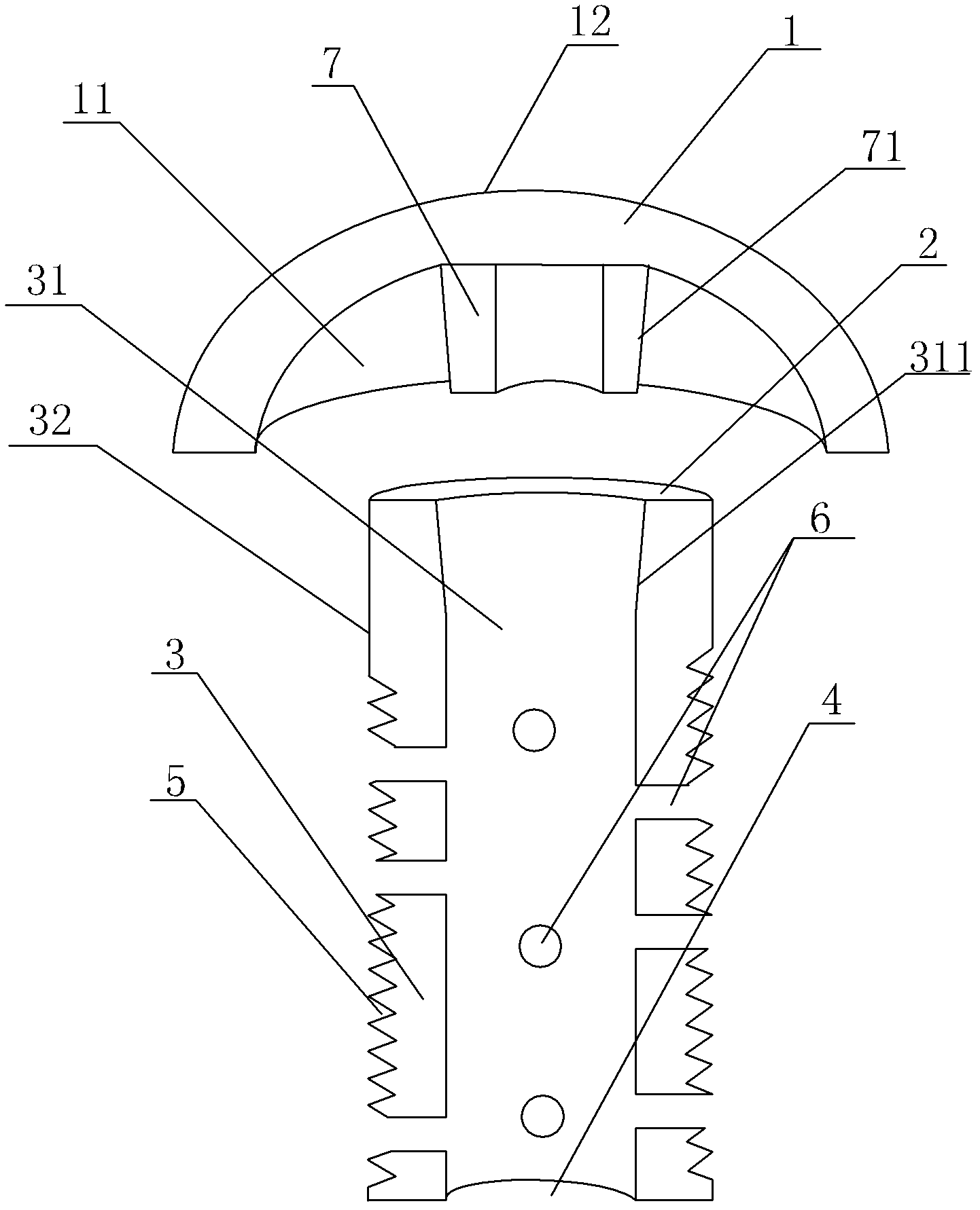
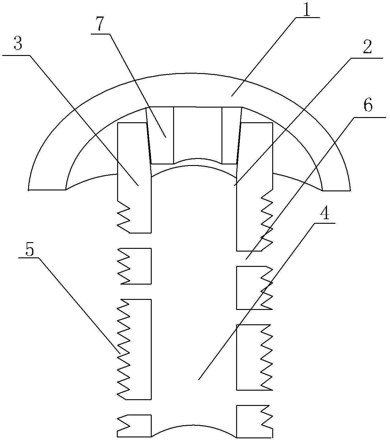
[0018] Such as figure 1 and figure 2 A biotype femoral head surface replacement prosthesis shown includes a single cup 1 and a central rod. The central rod is a hollow hollow tube 2 composed of a lumen 4 and a tube wall 3. The thickness of the tube wall 3 is 0.6 cm. The diameter of the cavity 4 is 1.3 cm, the tube wall 3 is provided with an external thread 5, and the tube wall 3 is provided with 10-18 growth through holes 6 communicating with the tube cavity 4, and the diameter of the growth through holes 6 is 0.3-0.5 mm , the single cup 1 is provided with an intubation tube 7 inserted into the lumen 4, the outer surface 71 of the intubation tube 7 is an inclined plane, the angle between the inclined plane and the vertical line is 20 degrees, and the inner wall 3 of the hollow tube 2 The surface 31 is provided with an inclined surface 311 matching the outer surface 71 of the cannula 7, and the angle between the inclined surface 311 and the vertical line is also 20 degrees, a...

Embodiment 2

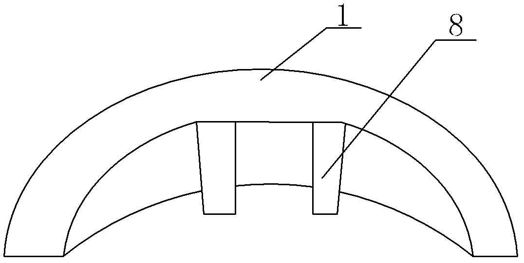
[0020] Basically the same as the embodiment, the only difference is as figure 2 The upper intubation tube 7 of the shown single cup 1 is replaced by a pair of tongue inserts 8, the thickness of the tube wall 3 is 0.5 cm, and the diameter of the lumen 4 is 1.0 cm.

Embodiment 3

[0022] It is basically the same as the embodiment, except that the thickness of the tube wall 3 is 1.0 cm, and the diameter of the lumen 4 is 1.5 cm.

[0023] In the above-mentioned embodiment, 10, 12, 15 or 18 through-holes can be set up. Under the load-bearing condition of the hollow tube, it is better to have more through-holes for growth, which is beneficial to the level of bone fusion inside and outside the hollow tube. To prevent the hollow tube from having insufficient load-bearing capacity when it is not fully fused with the femur, we selected a range of 10-18 after biomechanical verification; its diameter can be 0.3, 0.4, or 0.5 mm, etc. Set the size of the growth through hole under the condition that the tube load allows.


PUM


Abstract

The invention discloses a biotype femoral head surface substitutive prosthesis, which comprises a single cup and a central rod, wherein the central rod is a hollow tube consisting of a tube cavity and a tube wall, the tube wall has external threads, the tube wall has 10 to 18 growing through holes communicated with the tube cavity, and the diameter of the growing through holes is 0.3 to 0.5 millimeters. Thus, during an operation, surface correction instead of cutting neck of femur is needed, the hollow tube is screwed into and fixed in a bone cavity of the neck of femur, the hollow tube is in screwed connection with the neck of femur, the hollow tube is firmly fixed with the neck of femur without filling bone cement, and thus, bone cement looseness caused by mechanical wear is prevented; and as biomechanic properties of original hip joint are kept by keeping the neck of femur, sclerotin is implanted into the tube cavity, the sclerotin in and out of the hollow tube grow in the growing through holes in a restore process and gradually fused together to fuse the hollow tube and the neck of femur together completely. Therefore, the neck of femur and the prosthesis are bonded firmly, the prosthesis can be used for a long time, and the service life of the prosthesis is prolonged.

Description

technical field [0001] The invention relates to an artificial hip joint prosthesis, in particular to a biological femoral head surface replacement prosthesis. Background technique [0002] Artificial hip joint prosthesis includes acetabular prosthesis and femoral head prosthesis, acetabular prosthesis and hip bone fixation, femoral head prosthesis and femoral bone fixation, can be used for femoral head surface replacement in patients with femoral head necrosis and femoral head fracture, lifting patient's quality of life. Hip joint surface replacement technology has a history of nearly 50 years, and there have been innovations in materials and structures. For example, the bioprosthesis is sprayed with hydroxyapatite or titanium powder on the bone contact surface, and forms a microporous surface layer (ie Surface roughness) can promote bone cells to grow into the micropores to eliminate the formation of fibrous membrane, help trabecular bone grow into, the interface between b...

Claims


Application Information

Patent Timeline
Patent Type & Authority Applications(China)
IPC IPC(8): A61F2/36
CPCA61F2/36A61F2002/30001
Inventor 张前法
Owner 张前法
Why Eureka
Try Eureka