Dehydrating device and dehydrating method

A dehydration device and drainage pipe technology, which is applied in the direction of the feeding/discharging device of the settling tank, the settling tank, etc., can solve the problems of difficult water removal and high moisture content of sludge, so as to avoid secondary pollution, reduce water content, reduce The effect of moisture

Active Publication Date: 2011-09-21
YUNNAN DAHONGSHAN PIPELINE
View PDF5 Cites 0 Cited by
  • Summary
  • Abstract
  • Description
  • Claims
  • Application Information

AI Technical Summary

Problems solved by technology

[0007] The present invention designs a dehydration device and its dehydration method, which solves the technical problem that the water coming out of the drain outlet is not easy to be discharged during drainage, resulting in a relatively high moisture content of the sludge at the drain outlet

Method used


Image

  • Dehydrating device and dehydrating method
  • Dehydrating device and dehydrating method
  • Dehydrating device and dehydrating method

Examples


Embodiment Construction

[0028] Combine below Figure 1 to Figure 3 , the present invention is further described:

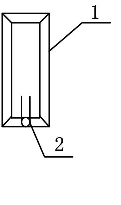
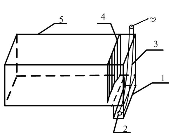
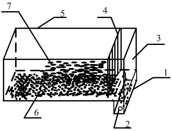
[0029] figure 1 and figure 2 A dehydration device of the present invention is disclosed in , comprising a tank body 5, a bottom settling tank 1 is provided on one side of the bottom of the tank body 5, and a drain outlet 2 is provided on the side wall of the bottom settling tank 1; There is also a floating object baffle 4 inside, and the floating object baffle 4 is arranged at the front end opposite to the bottom settlement tank 1 .

[0030] The tank body 5 is a cuboid welded by common carbon steel plates, except that the other five sides of the upper end are completely closed. The tank body is 1200mm long, 400mm wide and 300mm high. A bottom settlement tank 1 with a length of 400mm, a width of 200mm and a height of 200mm is welded on the right bottom of the tank body 5, and the bottom settlement tank 1 is welded below the tank body 5 to effectively remove water in the tank body 5. ...


PUM


Abstract

The invention relates to a dehydrating device and a dehydrating method. The dehydrating device comprises a tank body (5), wherein one side of the bottom of the tank body (5) is provided with a bottom settling tank (1); the side wall of the bottom settling tank is provided with a water outlet (2); and a floater baffle plate (4) is arranged in the tank body (5) and at the front end opposite to the bottom settling tank (1). The bottom settling tank is arranged at the bottom of the tank body, so slurry or ore pulp can be more fully settled, and the water content of a solid material can be effectively reduced. The floater baffle plate is arranged, so the whole device can more effectively prevent floating wastes from being settled, and water brought by the floating wastes is greatly reduced; meanwhile, the device has a simple structure, the using method is simple, and energy and manpower are saved because a water pump is not required to be used.

Description

technical field [0001] The invention relates to a solid material dehydration device, in particular to a dehydration device for slurry materials such as coal slurry, sludge and tailings. Background technique [0002] At this stage, the dehydration methods of slurry materials such as coal slurry, mud slurry, ore slurry and tailings slurry mainly include the following methods: First, use open air drying and natural air drying. Second, use a filter press to squeeze out the moisture in the slurry material. Third, use a ceramic filter or filter cloth machine to make the slurry realize solid-liquid separation under the action of negative pressure, and finally achieve the purpose of dehydrating the slurry material. [0003] However, the following disadvantages will occur when using the above several dehydration methods: [0004] 1. When using the open air drying method and natural air drying method. It will be restricted by unfavorable factors such as large drying area and long t...

Claims


Application Information

Patent Timeline
IPC IPC(8): B01D21/02B01D21/24
Inventor 安建普光跃潘春雷李斌李如学赵科宋云明郭悦波李伟军
Owner YUNNAN DAHONGSHAN PIPELINE
Why Eureka
Try Eureka