Lower spraying laminar flow cooling device

A laminar cooling device and cooling device technology, applied in metal processing equipment, metal rolling, manufacturing tools, etc., can solve the problems of reducing the edge of the strip, uneven cooling distribution, and high water consumption of the device. consumption, avoid water waste, ensure the effect of the shape

Active Publication Date: 2011-09-21
BAOSHAN IRON & STEEL CO LTD
View PDF8 Cites 6 Cited by
  • Summary
  • Abstract
  • Description
  • Claims
  • Application Information

AI Technical Summary

Problems solved by technology

[0021] The object of the present invention is to provide a down-spray laminar flow cooling device, which can solve the problem of high water consumption in the existing device, and at the same time enable the cooling width of the laminar cooling water to be adjusted according to the strip width; According to the cooling process requirements of different widths of steel, the gap laminar flow corresponding to the lower surface of the strip channel width should be established to reali

Method used


Image

  • Lower spraying laminar flow cooling device
  • Lower spraying laminar flow cooling device
  • Lower spraying laminar flow cooling device

Examples


Embodiment Construction

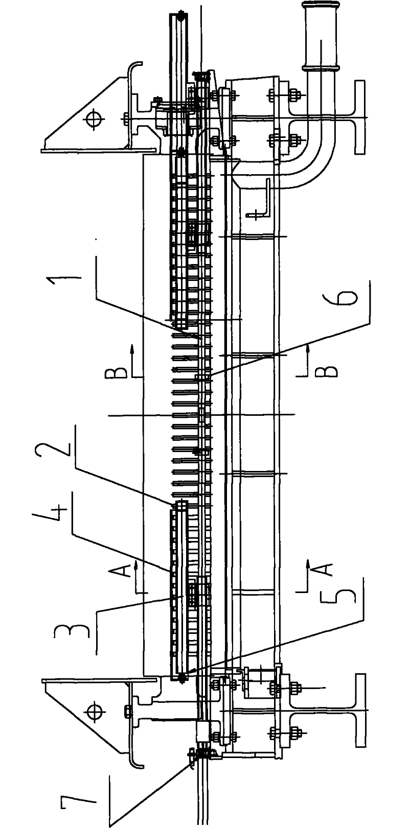
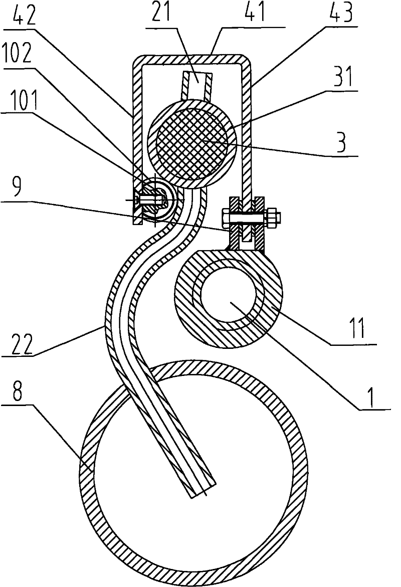
[0051] In this example will combine Figure 2-Figure 5 A preferred embodiment of the present invention is introduced.

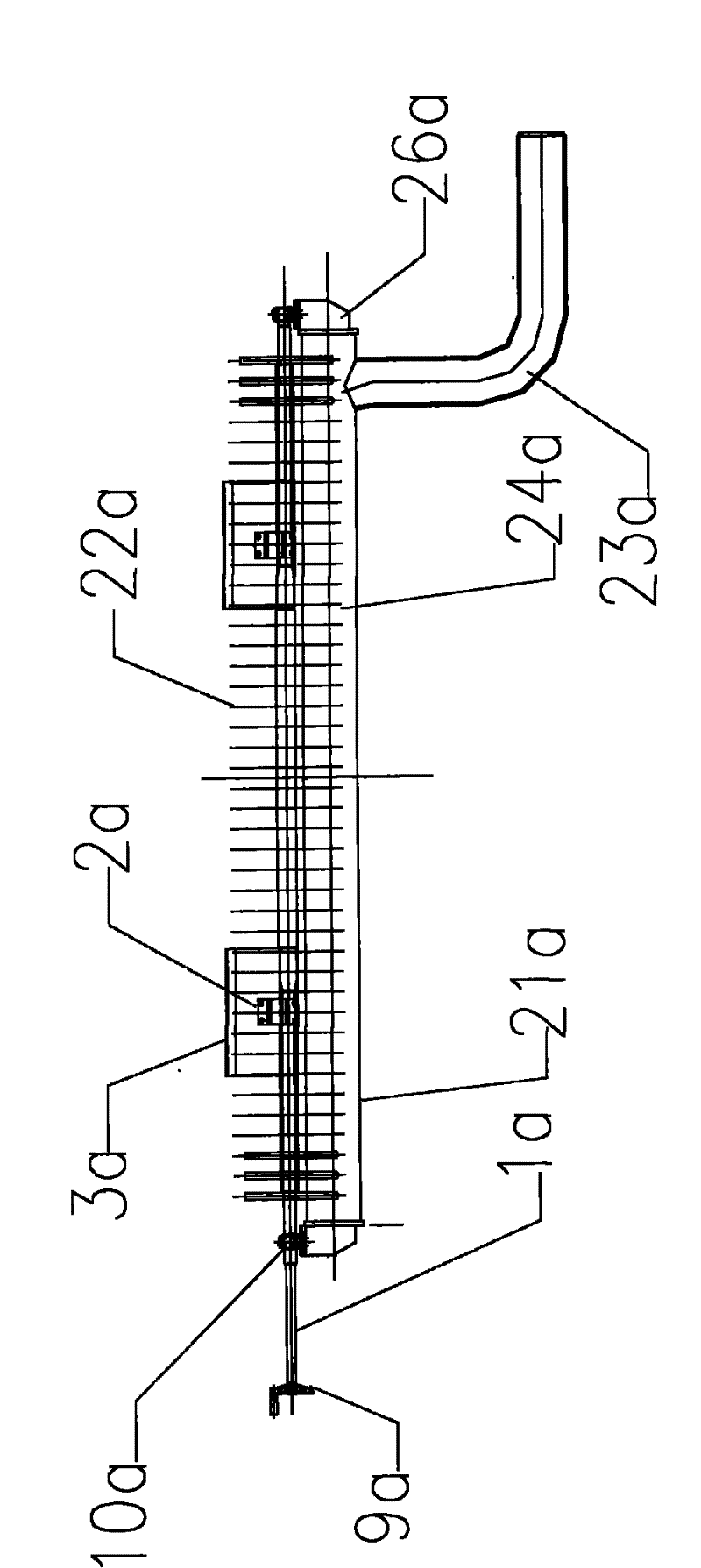
[0052] The down spray laminar flow cooling device in the present embodiment comprises several groups of down spray devices, each group of down spray devices such as figure 2 and image 3 The shown includes: a header 8 fixedly arranged along the running direction of the vertical strip; a number of gooseneck nozzles 2 are evenly distributed on the header 8 along the axial direction of the header, and the gooseneck nozzles 2 are connected to the header 8; Two plunger pipes 31 are respectively fixedly arranged above the left and right ends of the manifold 8, and the two plunger pipes 31 run through a plurality of gooseneck nozzles 2 evenly distributed at both ends of the manifold 8 respectively, and the gooseneck nozzles 2 are sprayed on respectively. 21 and the lower nozzle pipe 22, the plunger pipe 31 is connected with the upper nozzle 21 and the lower nozzl...


PUM


Abstract

The invention discloses a lower spraying laminar flow cooling device. The device comprises a plurality of groups of lower spraying devices, wherein each group of lower spraying device comprises a collecting pipe, two plunger pipes, two plungers and two U-shaped covers; the collecting pipe is fixedly arranged along a direction vertical to the operation direction of strip steel; a plurality of goose neck spray pipes are uniformly distributed on the collecting pipe along the axial direction; the two plunger pipes are fixedly arranged above the two ends of the collecting pipe respectively, pass through the plurality of goose neck spray pipes which are uniformly distributed at the two ends of the collecting pipe respectively, divide the goose neck spray pipes into upper nozzles and lower spraypipes, and are communicated with the upper nozzles and the lower spray pipes of the goose neck spray pipes through a plurality of through holes; the two plungers are arranged in the two plunger pipesrespectively; the two U-shaped covers are covered outside the two plungers in a mode that openings are downward; and the plungers are connected with driving devices through the U-shaped covers, so that movement in the axial direction is realized, the through holes are blocked, and cooling water quantity is adjusted.

Description

technical field [0001] The invention relates to a laminar flow cooling device, in particular to a width-adjustable downward spray laminar flow cooling device used in hot rolling laminar flow cooling. Background technique [0002] The laminar flow cooling device is used in the hot rolling and continuous rolling mill production lines of iron and steel enterprises. Its main function is to quickly cool the strip steel exported from finish rolling according to the target temperature set by coiling to ensure the product performance of the strip steel. [0003] Taking Baosteel 2050 hot rolling plant as an example, its laminar flow cooling device has a total of 76 sets of cooling headers (corresponding to the upper and lower sets). Among them, the first 68 groups are the main cooling section, and the last 8 groups are the refined cooling section. It is generally divided into several cooling zones, and each cooling zone has its own main cooling section and the cooling section of the...

Claims


Application Information

Patent Timeline
IPC IPC(8): B21B45/02
Inventor 王军
Owner BAOSHAN IRON & STEEL CO LTD
Why Eureka
Try Eureka