Micro-texture self-lubricating drilling bit and manufacturing method thereof

A micro-textured, self-lubricating technology, applied in drilling/drilling equipment, drilling repair, tool manufacturing, etc., can solve problems such as drilling temperature rise, drill wear, friction increase, etc.

Inactive Publication Date: 2011-09-21
SHANDONG UNIV
View PDF7 Cites 34 Cited by
  • Summary
  • Abstract
  • Description
  • Claims
  • Application Information

AI Technical Summary

Problems solved by technology

However, during dry drilling, due to the lack of lubrication and cooling of the cutting fluid, the friction conditions between the drill bit workpiece

Method used


Image

  • Micro-texture self-lubricating drilling bit and manufacturing method thereof
  • Micro-texture self-lubricating drilling bit and manufacturing method thereof
  • Micro-texture self-lubricating drilling bit and manufacturing method thereof

Examples


Embodiment 1

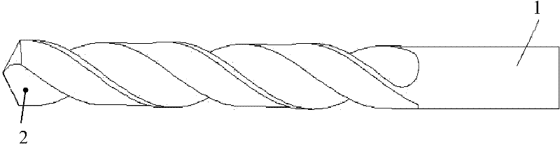
[0018] A micro-textured self-lubricating drill bit, the material of which is high-speed steel, and a plurality of microholes for storing solid lubricant in the cutter-chip contact area of ​​the drill bit rake face. Its preparation method is as follows:

[0019] 1. Use laser processing technology to process 6 micro-holes in the rake face tool-chip contact area of ​​the drill bit. The diameter of the micro-holes is 100 μm, and the depth of the micro-holes is 100 μm.

[0020] 2. Fill each micropore with a solid lubricant with a particle size of 1.0 μm, and the solid lubricant is composed of 50wt.% MoS 2 , 30wt.%WS 2 and 20wt.% TaS 2 The powder is blended and blended into a viscous shape with stearic acid.

Embodiment 2

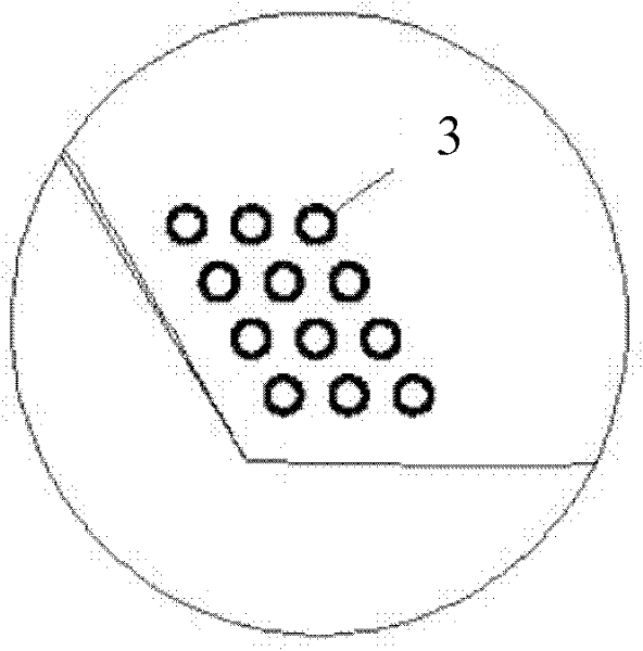
[0022] A micro-textured self-lubricating drill bit, the material of which is high-speed steel, and a plurality of microholes for storing solid lubricant in the cutter-chip contact area of ​​the drill bit rake face. Its preparation method is as follows:

[0023] 1. Use laser processing technology to process 15 micro-holes in the rake face tool-chip contact area of ​​the drill bit. The diameter of the micro-holes is 50 μm, and the depth of the micro-holes is 50 μm.

[0024] 2. Fill each micropore with a solid lubricant with a particle size of 0.5 μm, and the solid lubricant is made of 40wt.% MoS 2 , 30wt.%WS 2 and 30wt.% TaS 2 The powder is blended and blended into a viscous shape with stearic acid.

Embodiment 3

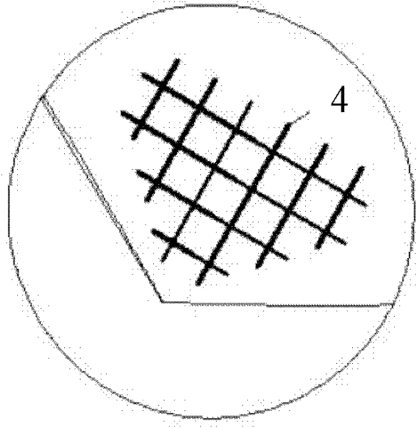
[0026] The utility model relates to a micro-textured self-lubricating drill bit. The material of the drill bit is cemented carbide, and the cutter-swarf contact area of ​​the drill bit rake face has a plurality of grid-shaped micro-grooves storing solid lubricant. Its preparation method is as follows:

[0027] 1. Use laser processing technology to process 10 grid-like micro-grooves in the tool-chip contact area on the rake face of the drill bit. The width of each micro-groove is 60 μm and the groove depth is 60 μm.

[0028] 2. Fill each micropore with a solid lubricant with a particle size of 0.6 μm, and the solid lubricant is made of 40wt.% MoS 2 , 40wt.%WS 2 and 20wt.% TaS 2 The powder is blended and blended into a viscous shape with stearic acid.


PUM

PropertyMeasurementUnit
Diameteraaaaaaaaaa
Pore depthaaaaaaaaaa
Particle sizeaaaaaaaaaa

Abstract

The invention belongs to the technical field of mechanical cutting tool manufacturing, and in particular relates to a micro-texture self-lubricating drilling bit and a manufacturing method thereof. A knife-chipping contact area of the rack face of the micro-texture self-lubricating drilling bit is provided with a plurality of micro-textures which are filled with a solid lubricant; during dry drilling, under the action of high temperature, the solid lubricant in the micro-textures is rapidly softened and is applied to the rack face of the drilling bit; a continuous solid lubricating layer is formed on the knife-chipping contact area of the rack face of the drilling bit, thereby being capable of preventing bonding, decreasing friction, reducing abrasion and prolonging the service life of the drilling bit. The micro-texture self-lubricating drilling bit can be widely applied to the drilling and machining of dry-type drilling and difficulty-machined materials, can overcome the environmental pollution caused by cutting fluid, realizes clean production and reduces the cost.

Description

1. Technical field [0001] The invention belongs to the technical field of mechanical cutting tool manufacturing, in particular to a micro-textured self-lubricating drill bit and a preparation method thereof. 2. Background technology [0002] In the drilling process, there are multiple friction pairs, including the friction pair composed of rake face, spiral groove and chips, and the friction pair composed of flank face, edge band, chisel edge and workpiece. During drilling, the friction between the rake face and the flank face of the drill bit and the chips and the workpiece is particularly severe, resulting in rapid wear of the drill bit. In addition, drilling is carried out in a relatively sealed environment. The cutting fluid required for traditional drilling cannot reach the drilling part in time, resulting in a decrease in the lubricity of drilling, increased friction, and a large amount of heat that cannot be discharged. cause the drill to fail. Moreover, the use of ...

Claims


Application Information

Patent Timeline
IPC IPC(8): B23B51/06B23P15/32
Inventor 邓建新连云崧吴泽亓婷
Owner SHANDONG UNIV
Why Eureka
Try Eureka