Electroplating device for lead wire framework

A technology of lead frame and electroplating device, which is applied in the direction of jewelry, etc., can solve the problems of affecting the quality of lead frame electroplating, low production efficiency, easy to cause pollution, etc., and achieve the effect of avoiding burning phenomenon, high yield rate and good uniformity

Active Publication Date: 2011-09-21
XIAMEN YONGHONG TECH
View PDF4 Cites 11 Cited by
  • Summary
  • Abstract
  • Description
  • Claims
  • Application Information

AI Technical Summary

Problems solved by technology

[0004] 1. Since the same lead frame product needs to be electroplated twice to complete, the production efficiency is low;
[0005] 2. It is easy to cause pollution during the two electroplating conversion p

Method used


Image

  • Electroplating device for lead wire framework
  • Electroplating device for lead wire framework
  • Electroplating device for lead wire framework

Examples


Example Embodiment

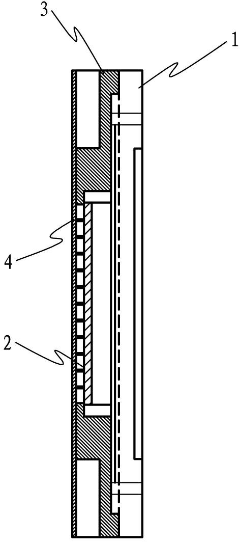
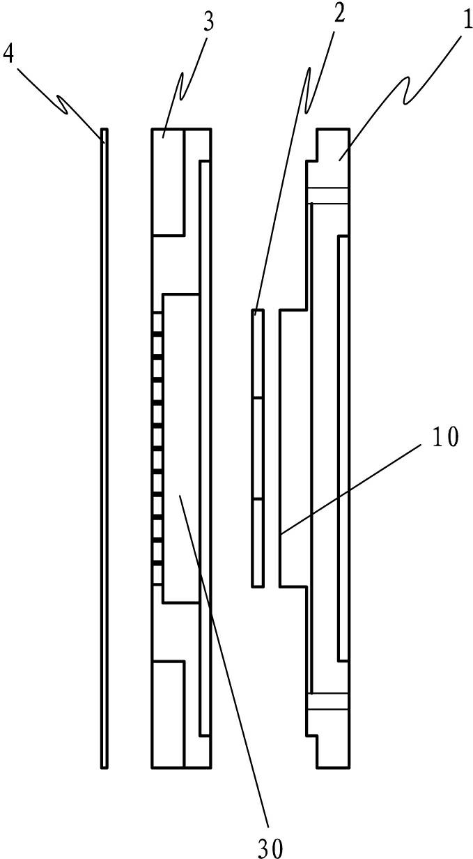
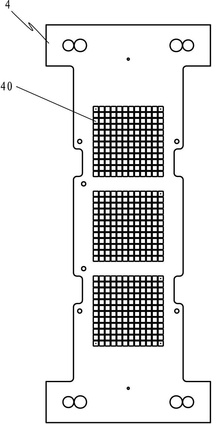
[0036] Example: see Figure 1 to Figure 16 , A lead frame electroplating device, from bottom to top sequentially includes a spray plate 1, an anode plate 2, a substrate 3, and a mask base plate 4. The mask base plate has a plurality of electroplating through holes 40 distributed in an array, such as image 3 As shown, the above-mentioned through holes respectively correspond to the electroplating unit areas (lead frame pads) on the lead frame, and the electroplating device completes the lead frame electroplating operation at one time through the electroplating solution spray circuit on the spray plate 1 and the anode plate 2.

[0037] See Figure 4 to Figure 7 There is a groove 30 on the substrate 3, and the bottom surface of the groove is provided with a plurality of through holes 301 superimposed on the plated through holes 40 of the mask base plate 4. The through holes on the two plates are square holes. The jet plate 1 has a protrusion 10 and a recess of the substrate. The tank...


PUM


Abstract

The invention discloses an electroplating device for a lead wire framework. The electroplating device comprises a spraying plate, an anode plate, a substrate and a mask base plate from bottom to top, wherein a plurality of electroplating through holes are formed on the mask base plate in an array manner; each through hole corresponds to an electroplating unit region on the lead wire framework; and the electroplating device finishes the lead wire framework electroplating work at a time through electroplating liquid spraying loops on the spraying plate and the anode plate. In the electroplatingdevice, the electroplating liquid is sprayed into a spraying runner and electroplated onto a welding disk region of the lead wire framework so as to finish all electroplating unit regions at a time; moreover, the uniformity and the electroplating quality are high; the residual electroplating liquid is collected by the runners of the loops so that the spraying path of the electroplating liquid cannot be influenced; in particular, the electroplating device is suitable for a plurality of lead wire frameworks; and a charring phenomenon can be avoided and the yield rate is high.

Description

technical field [0001] The invention discloses an electroplating device for a lead frame, which belongs to the technical field of lead frame processing and manufacturing according to the International Patent Classification (IPC), and in particular relates to an electroplating auxiliary device for a QFN-four-side leadless flat package. Background technique [0002] At present, multi-rows of semiconductor integrated circuit lead frames (including QFN and other packages) is a development trend in the industry, especially for the lead frames of QFN packages, the electroplating requirements are high, and the adjacent electroplating unit areas of multi-row frame products are close, further Increased the difficulty of electroplating. [0003] The applicant's previous applications CN101864586A and CN201729904U respectively disclosed a lead frame electroplating method and the electroplating auxiliary equipment used, wherein the electroplating process is to divide all the unit windows...

Claims


Application Information

Patent Timeline
IPC IPC(8): C25D5/08C25D5/02C25D7/00
Inventor 苏月来林桂贤王锋涛李南生王康
Owner XIAMEN YONGHONG TECH
Why Eureka
Try Eureka