Gear-driven internal combustion engine

A gear transmission mechanism and gear transmission technology, applied in the direction of transmission devices, machines/engines, friction transmission devices, etc., can solve the problem of low power transmission efficiency

Inactive Publication Date: 2013-10-30
舒锦海
View PDF4 Cites 3 Cited by
  • Summary
  • Abstract
  • Description
  • Claims
  • Application Information

AI Technical Summary

Problems solved by technology

[0002] In the history of more than one hundred years of development of reciprocating internal combustion engines, the crankshaft and connecting rod are used to output power, although the efficiency of power transmission is not high

Method used


Image

  • Gear-driven internal combustion engine
  • Gear-driven internal combustion engine
  • Gear-driven internal combustion engine

Examples


Embodiment 1

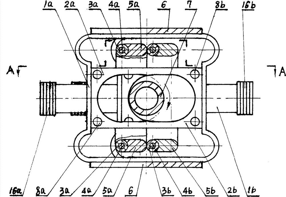
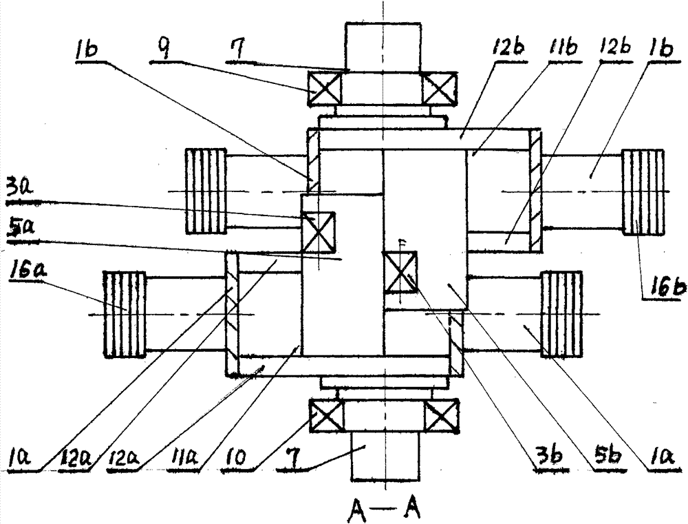
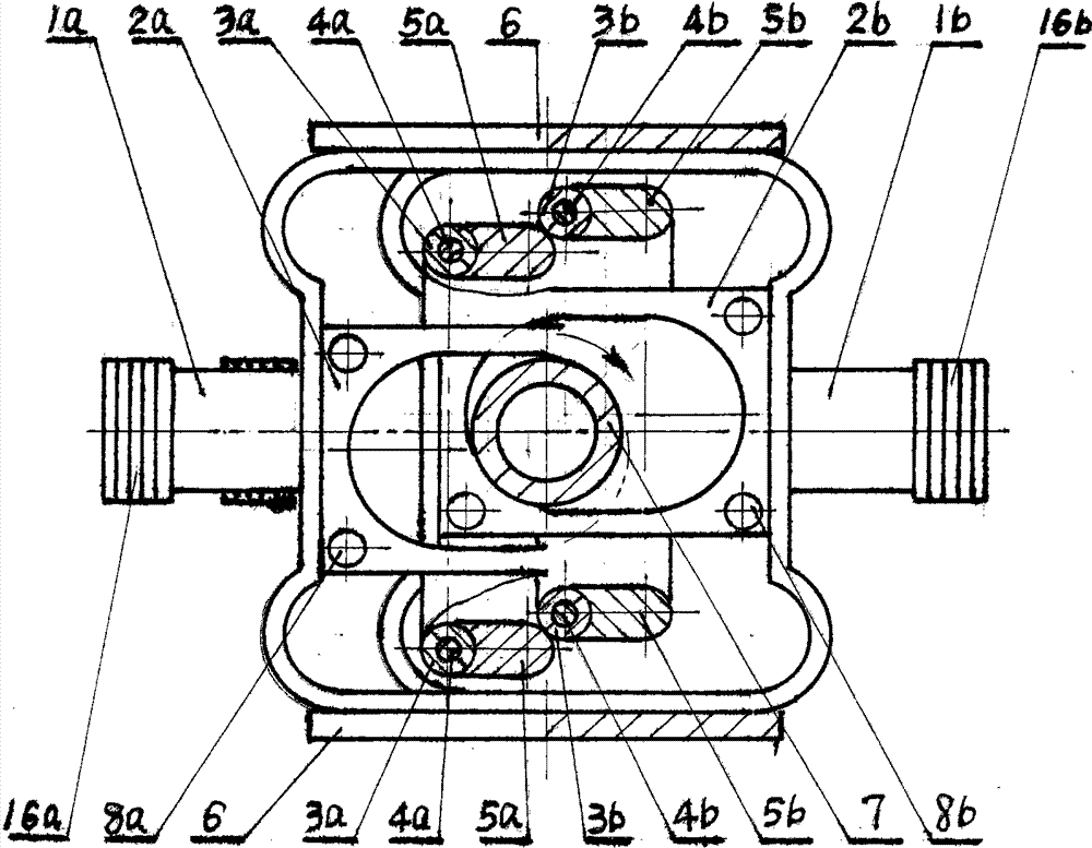
[0039] Embodiment 1: 1.6 liters of four-cylinder four-stroke gear transmission internal combustion engine, see Figure 1 to Figure 7 .

[0040] The bore of the internal combustion engine is 81mm, the stroke is 77.1mm, and the displacement is 1589cc. Such as Figure 7 As shown, the cylinder head of the internal combustion engine adopts a thin design, so that the width of the horizontally opposed internal combustion engine is controlled at 800mm. Most car engine compartments have a width of 900mm and have installation space. If the engine is mounted longitudinally so that the piston moves in the same direction as the car runs, the car will run more smoothly.

[0041] After more than one hundred years of development, the technology of internal combustion engines for vehicles has been very mature. In order to inherit all the advanced technologies and scientific research achievements of modern internal combustion engines, the gear transmission mechanism of the present invention...

Embodiment 2

[0045] Embodiment 2: gear transmission hydraulic motor.

[0046] Such as figure 1 As shown, the piston of the gear transmission mechanism is equipped with a hydraulic cylinder and a reversing valve, which can push the transmission shaft [7] to rotate under the action of pressure oil. The output effective power is high and the output torque is large.

Embodiment 3

[0047] Embodiment 3: gear transmission pump.

[0048] Such as figure 1 As shown, the gear transmission mechanism is driven by the prime mover to rotate the transmission shaft [7], which drives the piston to make a reciprocating linear motion, and sucks and pumps the medium in the cylinder through the one-way valve group.

[0049] Practical example 4, ideal geared internal combustion engine, see Figure 8 to Figure 11 .

[0050] The gear sleeve assembly [2a] and the gear sleeve assembly [2b] of an ideal geared internal combustion engine are the same, and the shape of the internal gear is a rectangle with four rounded corners, and the index circles of the two opposite quarter internal gears The pitch circle radius of the gear on the radius and transmission shaft [7] is equal. As mentioned earlier, the shape of the hub is the same as the centerline outline of the teeth of the internal gear. The shape of positioning slide block [15a] and positioning slide block [15b] is equal...


PUM


Abstract

The invention relates to a gear-driven mechanism which can run reversely and convert the reciprocating rectilinear movement into the rotation toward the same direction. In the technical scheme, the drive of a gear sleeve and a gear is adopted for replacing the drive of a crankshaft and a connecting rod. The gear-driven mechanism can be widely applied to vehicle internal combustion engines, marine low-speed diesel engines, tank engines, hydraulic motors, pump and other machines. As a gear-driven internal combustion engine imitates the working condition of a crankshaft-driven internal combustion engine at the strong deflagration stage of the burning and combustion of fuels, the gear-driven mechanism also can meet the constant volume combustion condition of a spark ignition type internal combustion engine and maintains the conversion efficiency of the heat engine cycle of the internal combustion engine. The gear-driven mechanism provides a doubled drive angle nearby a top dead center so that the mechanical efficiency is substantially increased. The ideal gear-driven internal combustion engine can really realize the constant volume combustion, blows up gas energy instantly and ensures that the cycle thermal efficiency reaches an ideal level.

Description

technical field [0001] The invention relates to a gear transmission mechanism capable of running in reverse and converting reciprocating linear motion into rotation in the same direction. In the technical scheme, the transmission of the gear sleeve and the gear is used to replace the transmission of the crankshaft and the connecting rod. The gear transmission mechanism can be widely used in internal combustion engines for vehicles, low-speed marine diesel engines, tank engines, hydraulic motors and pumps and other machinery. Background technique [0002] In the history of more than one hundred years of development of reciprocating internal combustion engines, crankshafts and connecting rods are used to output power, although the efficiency of power transmission is not high. [0003] According to the description of application number 200510032875.0, titled "Opposed Internal Rack Pushing Intermittent Gear Internal Combustion Engine" and application number 200610092074.8, titl...

Claims


Application Information

Patent Timeline
Patent Type & Authority Patents(China)
IPC IPC(8): F02B75/28F16H19/04
Inventor 舒锦海
Owner 舒锦海
Why Eureka
Try Eureka