Proton exchange membrane fuel cell flow field structure

A proton exchange membrane, fuel cell technology, applied in fuel cells, fuel cell parts, circuits, etc., can solve the problems of low cost, reduce concentration polarization, widen social benefits and market prospects, and improve performance. Effect

Inactive Publication Date: 2011-09-28
SHENYANG JIANZHU UNIVERSITY
View PDF3 Cites 11 Cited by
  • Summary
  • Abstract
  • Description
  • Claims
  • Application Information

AI Technical Summary

Problems solved by technology

[0008] In order to solve the above problems, the present invention provides a flow field flow channel that drains quickly and is not prone to blockage of the flow channel, short circuit or channeling, reduces concentration polarization, achieves excellent battery performance, uniform current density distribution, and low cost. Flow Field Structure of a Proton Exchange Membrane Fuel Cell

Method used


Image

  • Proton exchange membrane fuel cell flow field structure
  • Proton exchange membrane fuel cell flow field structure
  • Proton exchange membrane fuel cell flow field structure

Examples


Embodiment 1

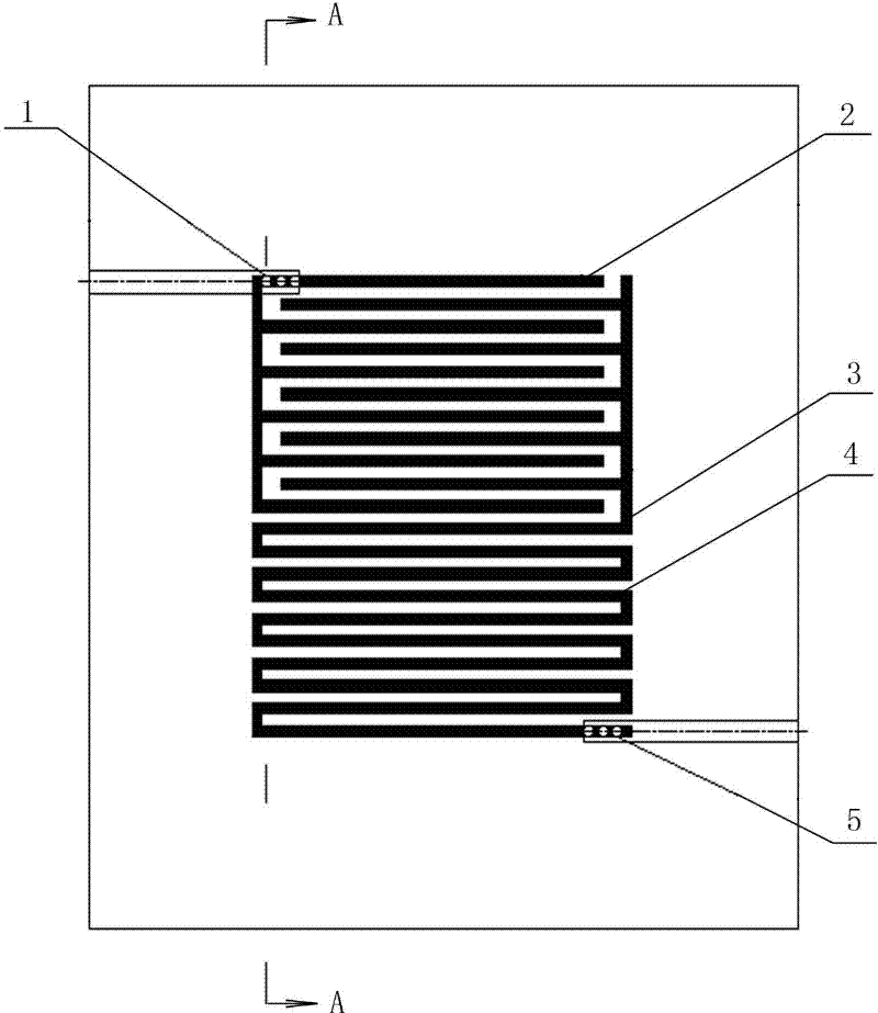
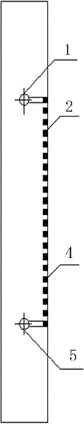
[0027] Such as figure 1 , figure 2 The shown flow field structure of a proton exchange membrane fuel cell according to an embodiment of the present invention includes an interdigitated flow field flow channel 2 and a serpentine flow field flow channel 4. The flow field plate adopts a graphite plate, and the width of each flow path is 1mm, the width of the ridge is 1mm. A total of 21 flow channels are set in the effective area of ​​the flow field on the same side of the flow field plate, and the flow channels are composed of interdigitated flow field flow channel 2 and serpentine flow field flow channel 4; The serpentine flow field flow channels 4 each account for 50% of the effective area of ​​the flow field, and the first flow channel at one end of the interdigitated flow field flow channel 2 is provided with a flow channel inlet hole 1; one end of the serpentine flow field flow channel 4 The last flow channel is provided with a flow channel air outlet 5, and the interdig...

Embodiment 2

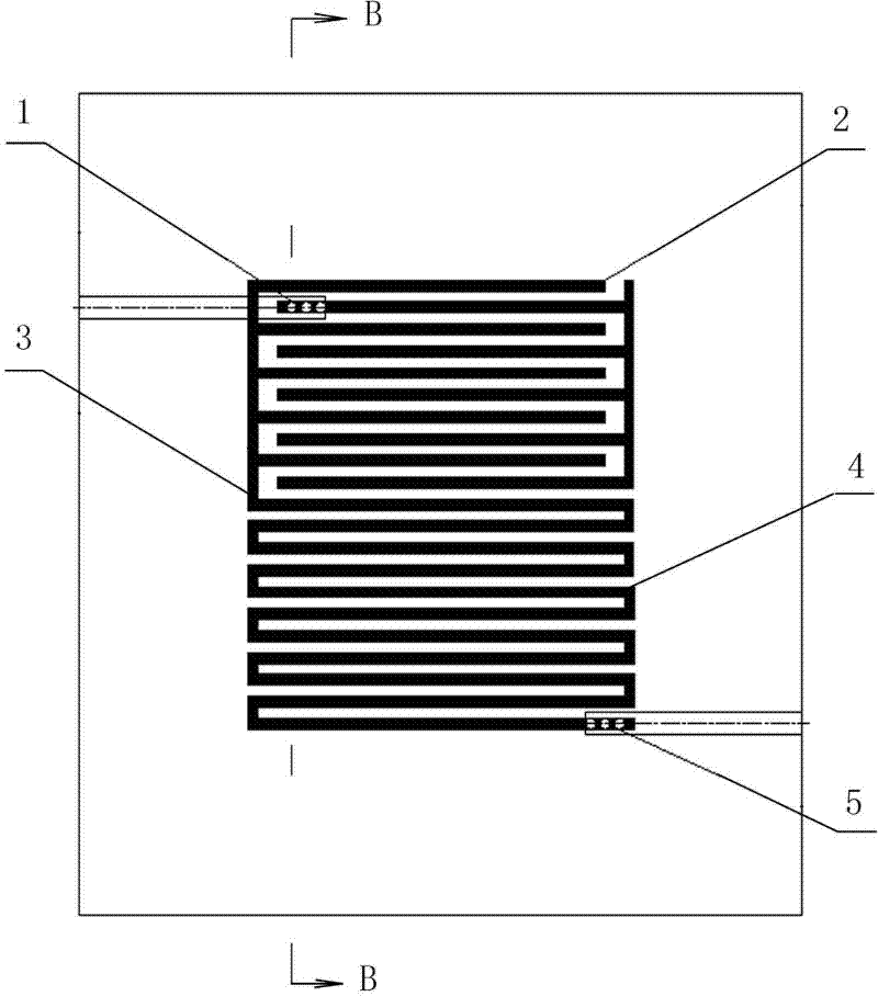
[0029] Such as image 3 , Figure 4 In the flow field structure of the proton exchange membrane fuel cell shown in another embodiment of the present invention, the second flow channel at one end of the interdigitated flow field flow channel 2 is provided with a flow channel inlet hole 1; the others are the same as in embodiment 1 ,No longer.


PUM


Abstract

The invention relates to a fuel cell flow field structure, in particular to a proton exchange membrane fuel cell flow field structure. The proton exchange membrane fuel cell flow field structure comprises an interdigitated flow field runner and a snake-shaped flow field runner; a plurality of runners consisting of the interdigitated flow field runner and the snake-shaped flow field runner are arranged on the same side of a flow field board; a runner air inlet hole is formed at a proper position of one end of the interdigitated flow field runner; a runner air outlet hole is formed at a proper position of one end of the snake-shaped flow field runner; and the interdigitated flow field runner and the snake-shaped flow field runner are connected with each other through a connecting runner. In the proton exchange membrane fuel cell flow field structure, the flow field runners are quick in water drainage; moreover, runner plugged, short circuit or channeling phenomena can be avoided; the current density distribution is uniform, the cell performance is higher, the structure is simple and rational, and the manufacturing cost is low; and the proton exchange membrane fuel cell flow field structure has wide social benefit and market prospect.

Description

technical field [0001] The invention relates to a fuel cell flow field structure, in particular to a proton exchange membrane fuel cell flow field structure, which belongs to the technical field of fuel cells. Background technique [0002] A fuel cell is an electrochemical device that can directly convert the chemical energy stored in fuel into electrical energy through an electrochemical reaction. It does not go through the heat engine process, is not limited by the Carnot cycle, and has high energy conversion efficiency (40-60%); has no impact on the environment, and hardly emits nitrogen and sulfide; the emission of carbon dioxide is low, which is 40% less than that of power plants %above. In addition, it also has the advantages of low noise, fast start-up, no corrosion, easy preparation and long service life. Due to these outstanding advantages, governments and large enterprises all over the world have invested a lot of manpower and material resources in researching an...

Claims


Application Information

Patent Timeline
Patent Type & Authority Applications(China)
IPC IPC(8): H01M8/02H01M8/0263
CPCY02E60/50Y02P70/50
Inventor 孙哲陈士忠孙红高晓佳金正南吴玉厚
Owner SHENYANG JIANZHU UNIVERSITY
Why Eureka
Try Eureka