Multi-frequency-range ceiling-type antenna

A ceiling antenna, multi-band technology, applied in the direction of the antenna, the resonant antenna, the mid-position feed between the antenna ends, etc., can solve the problem of single frequency coverage of the ceiling antenna, reduce the back radiation, and increase the working frequency band. , the effect of strong mechanical strength

Inactive Publication Date: 2011-09-28
孙全辉
View PDF0 Cites 13 Cited by
  • Summary
  • Abstract
  • Description
  • Claims
  • Application Information

AI Technical Summary

Problems solved by technology

[0003] Technical problem: the purpose of the present invention is to solve the problem of single frequency coverage of the existing ceiling antenna, and use a ceiling antenna to simultaneously realize the coverag

Method used


Image

  • Multi-frequency-range ceiling-type antenna
  • Multi-frequency-range ceiling-type antenna
  • Multi-frequency-range ceiling-type antenna

Examples


Embodiment Construction

[0020] The technical scheme of the present invention is described in detail below in conjunction with accompanying drawing:

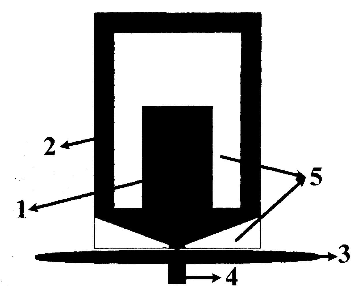
[0021] Such as figure 1 As shown, a multi-band ceiling antenna includes a first radiator 1, a second radiator 2, a circular metal plate 3, a coaxial feed system 4, a supporting medium 5, and a circular metal plate arranged horizontally The middle part of the lower end surface of 3 is provided with a coaxial feed system 4, and the middle part of the upper end surface of the circular metal plate 3 is provided with a second radiator 2, and the upper part of the second radiator 2 is set with a U-shaped first radiator 1, and the second radiator A supporting medium 5 is set between 2 and the circular metal disc 3 .

[0022] Both the first radiator 1 and the second radiator 2 of the present invention are composed of thin copper foils etched on the supporting medium 5, and their bottoms are connected in parallel near the feeding coaxial side, and are fed by th...


PUM


Abstract

The invention discloses a multi-frequency-range ceiling-type antenna. The multi-frequency-range ceiling-type antenna consists of a first radiating body, a second radiating body, a round metal plate, a coaxial feed system and a supporting medium, wherein the first radiating body and the second radiating body are etched by a thin copper foil on the surface of the medium, connected in parallel with each other at the bottom and fed by a co-axis; and the round metal plate consists of a metal sheet with a proper thickness and has a function of an electromagnetic horizontal plane. On the one hand, the size of each radiating body of the antenna can be reduced effectively, and on the other hand, forward radiation of the antenna can be enhanced and backward radiation of the antenna can be weakened. The feed co-axis passes through the horizontal plane from the lower side of the horizontal plane and feeds the radiating bodies, so a coaxial external conductor is electrically connected with the horizontal plane; and an inner conductor passes through a central round gap of the horizontal plane and is directly connected with the radiating bodies electrically. The coaxial impedance is equal to 50 ohms, so the multi-frequency-range ceiling-type antenna can be conveniently cascaded with other microwave systems and is applied to actual engineering. The multi-frequency-range ceiling-type antenna is massive in working frequency, so that the problem that the conventional ceiling-type antenna is single in frequency coverage is solved effectively.

Description

technical field [0001] The invention relates to a ceiling-mounted antenna, in particular to a ceiling-mounted antenna capable of working in multiple frequency bands, which can simultaneously provide coverage of multiple frequency bands and multi-standard mobile communication signals, and realize GSM900MHz, GSM1800MHz, PCS1900MHz and ISM2.4GHz with a single antenna signal coverage. Background technique [0002] The ceiling antenna is a kind of mobile communication antenna, which is mainly used to achieve indoor signal coverage. Indoors, the wireless signal is shielded or attenuated by building materials, resulting in weak signal strength, which affects signal reception and call quality. Therefore, in hotels, guesthouses, office buildings, conference venues and other occasions, ceiling antennas are used to enhance signal coverage. Common ceiling antennas usually use monopole antenna technology, which is relatively simple in design and widely used. However, the monopole ante...

Claims


Application Information

Patent Timeline
IPC IPC(8): H01Q1/36H01Q5/00H01Q9/28H01Q5/28H01Q5/307
Inventor 孙全辉
Owner 孙全辉
Why Eureka
Try Eureka