Microbiological fuel cell
A fuel cell and microbial technology, applied in the direction of biochemical fuel cells, etc., can solve the problems of environmental pollution, high processing cost, large processing capacity, etc., and achieve the effect of simple device structure, simple method and effective utilization
- Summary
- Abstract
- Description
- Claims
- Application Information
AI Technical Summary
Problems solved by technology
Method used
Image

Examples
Embodiment 1
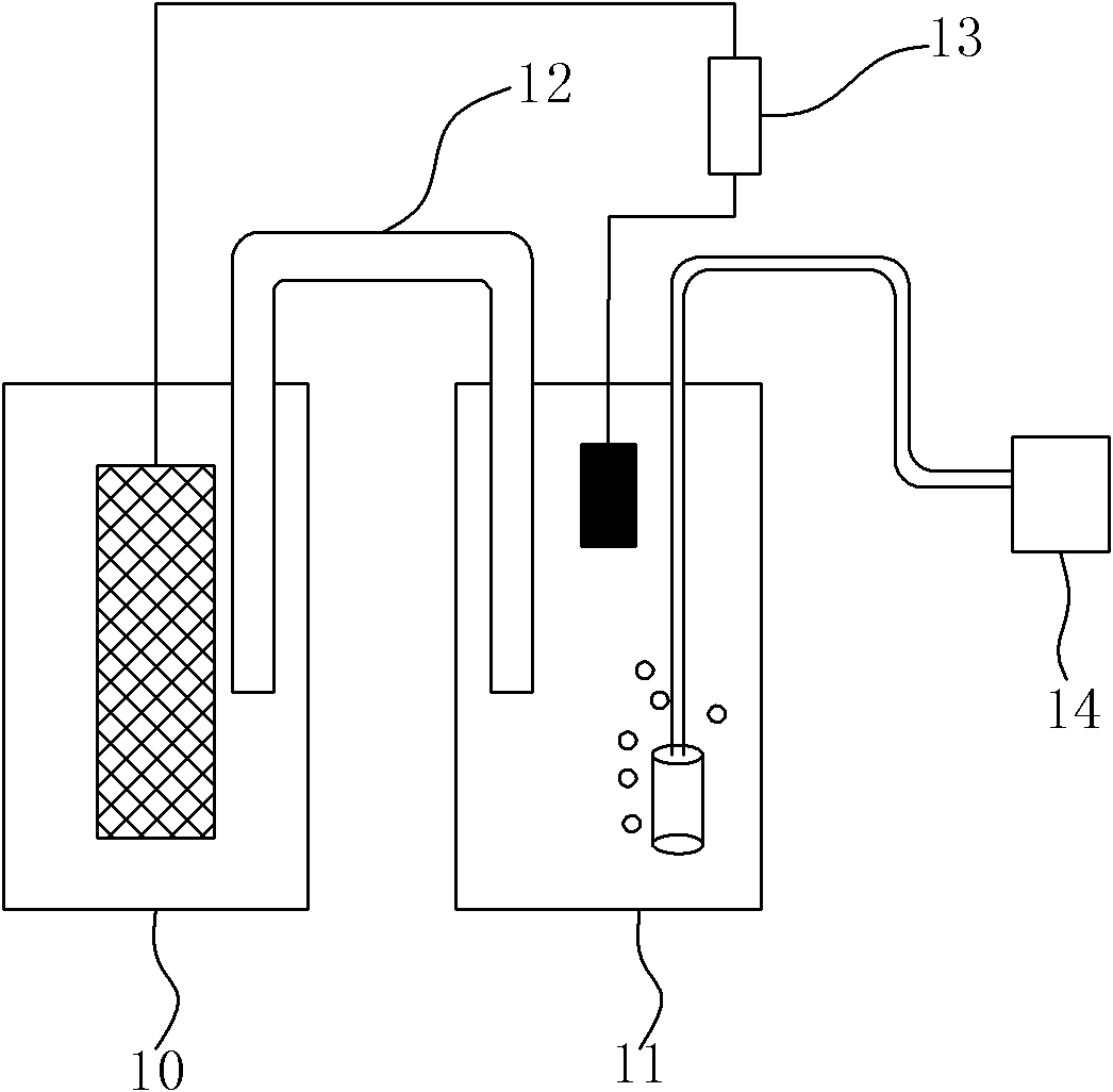
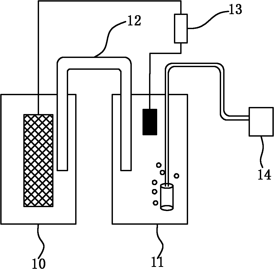
[0014] The microbial fuel cell includes: the anode chamber is equipped with organic waste, water and domesticated anaerobic sludge inside the anode chamber, the mass ratio of the three is about 5:3:1, the anode chamber is isolated from the air, and the interior is an anaerobic environment. The cathode chamber is composed of disodium hydrogen phosphate and sodium dihydrogen phosphate buffer solution, the concentration of the two is 0.1mol / L, and the volume ratio is 3:2. The cathode maintains an aerobic environment through aeration. connected by a salt bridge.
Embodiment 2
[0016] The microbial fuel cell includes: the anode chamber is equipped with organic waste, water and domesticated anaerobic sludge inside the anode chamber, the mass ratio of the three is about 4:2:1, the anode chamber is isolated from the air, and the interior is an anaerobic environment. The cathode chamber is composed of disodium hydrogen phosphate and sodium dihydrogen phosphate buffer solution, the concentration of the two is 0.3mol / L, and the volume ratio is 2:1. The cathode maintains an aerobic environment through aeration. connected by a salt bridge.
Embodiment 3
[0018] The microbial fuel cell includes: the anode chamber is equipped with organic garbage, water and domesticated anaerobic sludge inside the anode chamber, the mass ratio of the three is about 4.5:2.5:1, the anode chamber is isolated from the air, and the interior is an anaerobic environment. The cathode chamber is composed of disodium hydrogen phosphate and sodium dihydrogen phosphate buffer solution, the concentration of the two is 0.2mol / L, and the volume ratio is 2.5:1.5. The cathode maintains an aerobic environment through aeration. connected by a salt bridge.
[0019] The above implementation examples show that: when the present invention uses organic waste to generate electricity, the maximum open circuit voltage is about 700-1100mV and the maximum power density is 35-55mw / m 2 , TOC (total organic carbon degradation rate) is about 20 to 35%. The method of the invention is simple, the device structure is simple, no pollution, and the organic waste is effectively util...
PUM
| Property | Measurement | Unit |
|---|---|---|
| Maximum power density | aaaaa | aaaaa |
Abstract
Description
Claims
Application Information
 - Generate Ideas
- Intellectual Property
- Life Sciences
- Materials
- Tech Scout
- Unparalleled Data Quality
- Higher Quality Content
- 60% Fewer Hallucinations
Browse by: Latest US Patents, China's latest patents, Technical Efficacy Thesaurus, Application Domain, Technology Topic, Popular Technical Reports.
© 2025 PatSnap. All rights reserved.Legal|Privacy policy|Modern Slavery Act Transparency Statement|Sitemap|About US| Contact US: help@patsnap.com