Composite high-efficiency high-flow servo valve

A composite, high-flow technology, applied in the field of servo valves, can solve the problems of large magnetic field excitation power, large positioning error, large output force of memory alloy deformation, etc., achieve high frequency response and high precision, compact structure, and large output force Effect

Inactive Publication Date: 2011-10-12
WUHAN UNIV OF SCI & TECH
View PDF4 Cites 22 Cited by
  • Summary
  • Abstract
  • Description
  • Claims
  • Application Information

AI Technical Summary

Problems solved by technology

[0006] Magnetic control memory alloy is a new type of material, which has the characteristics of fast response of giant magnetostrictive materials, large deformation of memory alloy and large output force. However, magnetic control memory alloy has the characteristics of difficulty in deformation recovery. Currently, there are two common solutions. One: First, it is realized by applying a magnetic field along the deformation and elongation direction of the component, but the excitation power of the required magnetic field is too large
The second is to place a return spring along the deformation direction. Although this method is easy to implement, it will reduce the output force of the magnetic control memory alloy element, cause a large positioning error, and slow down the dynamic response speed.
However, the throttling area of ​​the valve is composed of a groove and a window on the valve sleeve, and the direction of input and output is changed mainly through rotational movement. The output waveform is limited during the working process, and the flow in a single direction cannot be continuous, which limits the scope of application.

Method used


Image

  • Composite high-efficiency high-flow servo valve
  • Composite high-efficiency high-flow servo valve
  • Composite high-efficiency high-flow servo valve

Examples


Embodiment 1

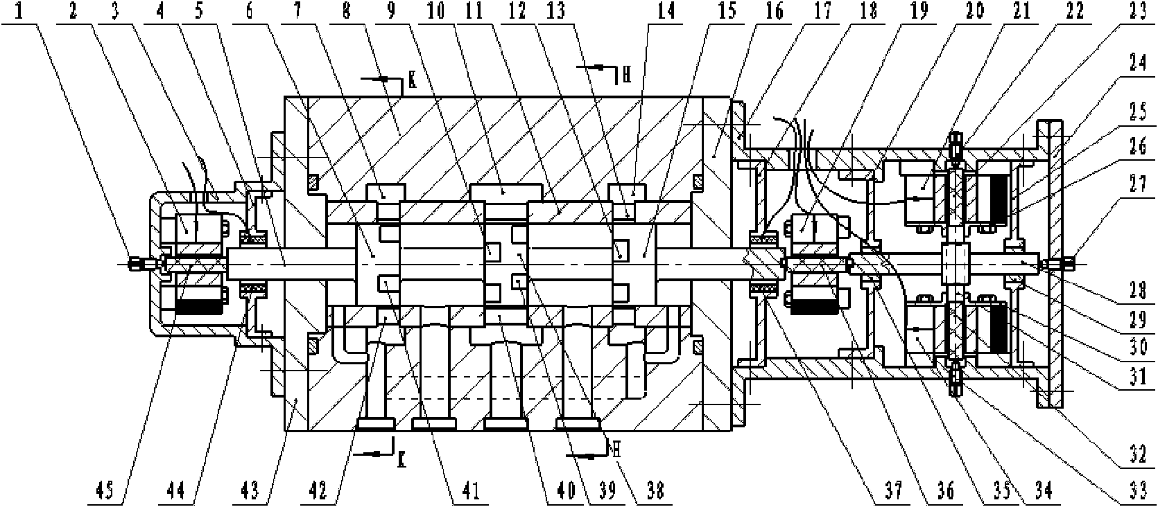
[0038] A composite high-frequency large-flow servo valve. The composite high-frequency large-flow servo valve such as figure 1 Shown: It consists of connecting the two ends of the compound flow valve with the left half of the compound magnetic control motor and the right half of the compound magnetic control motor respectively.

[0039] The structure of the left half of the composite magnetic control motor is: the first electromagnetic converter 2 and the displacement sensor 44 are arranged concentrically in the left housing 3 from left to right, and the first electromagnetic converter 2 is fixedly installed on the left housing. The inner wall of the body 3, the first magnetic memory alloy 45 passes through the central hole of the first electromagnetic converter 2, and the left zero adjustment screw contacts the left end face of the first magnetic memory alloy 45 through the left housing 3; the displacement sensor 44 passes through The first bracket 4 is fixedly installed on ...

Embodiment 2

[0057] A composite high-frequency large-flow servo valve. structured as figure 1 Shown: except following technical parameter, all the other are with embodiment 1.

[0058] The valve body 8 is evenly provided with a left annular groove 7, a middle annular groove 10 and a right annular groove 14, and 5 to 8 plain lines are evenly provided on the valve sleeve 11, and each plain line on the valve sleeve 11 is respectively provided with There are left window 42, middle window 40 and right window 13, and each left window 42, middle window 40 and right window 13 corresponds to left annular groove 7, middle annular groove 10 and right annular groove 14 respectively.

[0059]There are 5 to 8 left shoulder square grooves 41 evenly distributed on the right edge of the left shoulder 6 cylindrical surface, and 5 to 8 middle shoulder left square grooves are evenly distributed on the left edge of the middle shoulder 38 cylindrical surface. Groove 9, there are 5~8 middle shoulder square gro...


PUM


Abstract

The invention relates to a composite high-efficiency high-flow servo valve. The technical scheme is as follows: the servo valve consists of a composite flow valve and a composite magnetic control motor, two ends of the composite flow valve are respectively connected with a left haft part and a right half part of the composite magnetic control motor. A first electromagnetic converter [2] and a displacement sensor [44] are concentrically arranged in a left shell [3] from left to right in sequence; a valve core [5] is movably arranged in a valve sleeve [11] that is fixed in a valve body [8]; an angle displacement sensor [37], a second electromagnetic converter [19], a left sliding bearing [35], a gear shaft [28] and a right sliding bearing [29] are concentrically arranged in a right shell [17] from left to right in sequence; one side of the gearing shaft [28] is provided with a rack [31] that is meshed with the gear shaft [28]; and one end of the valve core [5] of the composite flow valve is in contact with an end surface of a first electromagnetic memorial alloy [45], and the other end of the valve core [5] is fixedly connected with a second magnetic control memorial alloy [36]. The servo valve has the characteristics of high frequency response, high reliability, high flow, small volume, small leakage, compact structure and high precision.

Description

technical field [0001] The invention belongs to the technical field of servo valves, in particular to a composite high-frequency and large-flow servo valve. Background technique [0002] The development trend of the high-frequency electro-hydraulic servo system is to develop toward a response frequency above 1000 Hz to meet the needs of vibration environment tests and material fatigue tests in the process of new product development. The operating frequency of the electro-hydraulic servo system mainly depends on the response frequency of the servo valve. [0003] At present, advanced high-frequency servo valves mostly adopt two structures: nozzle-baffle type and jet tube type. The nozzle-baffle type is characterized by simple structure, small volume, small moment of inertia, small driving force required, no friction, and high sensitivity; but its median leakage is large and output flow is small; the aperture of the fixed orifice and the nozzle The gap between the baffles is...

Claims


Application Information

Patent Timeline
Patent Type & Authority Applications(China)
IPC IPC(8): F15B13/02F16K31/06F16K31/04F16K31/54
Inventor 涂福泉陈奎生傅连东曾良才欧阳惠许仁波陈新元赵振飞蒋俊任印美周雯娟刘春雨
Owner WUHAN UNIV OF SCI & TECH
Why Eureka
Try Eureka