High-power simplified electrolytic and electroplating high-frequency switch power supply and control method thereof

A high-frequency switching power supply, electrolytic plating technology, applied in control/regulation system, output power conversion device, DC power input conversion to DC power output, etc., can solve the problem of increased capacity of power transformer switches, large diode rectifier circuits, Problems such as large harmonic content in the power grid, to achieve the effects of suppressing current disturbances, realizing high-efficiency utilization, and good output waveforms

Active Publication Date: 2011-10-19
HUNAN UNIV
View PDF4 Cites 21 Cited by
  • Summary
  • Abstract
  • Description
  • Claims
  • Application Information

AI Technical Summary

Problems solved by technology

The traditional thyristor or diode rectifier circuit is very large and bulky. If Gordon switching power supply technology is adopted, its volume and weight will be greatly reduced, and it can greatly improve power utilization efficiency, save materials, reduce costs, and achieve high-efficiency power consumption and Combination of high-quality electricity
[0003] For large-scale electrolytic electroplating power supplies, the traditional electroplating electrolytic DC power supply adopts the thyr

Method used


Image

  • High-power simplified electrolytic and electroplating high-frequency switch power supply and control method thereof
  • High-power simplified electrolytic and electroplating high-frequency switch power supply and control method thereof
  • High-power simplified electrolytic and electroplating high-frequency switch power supply and control method thereof

Examples


Embodiment Construction

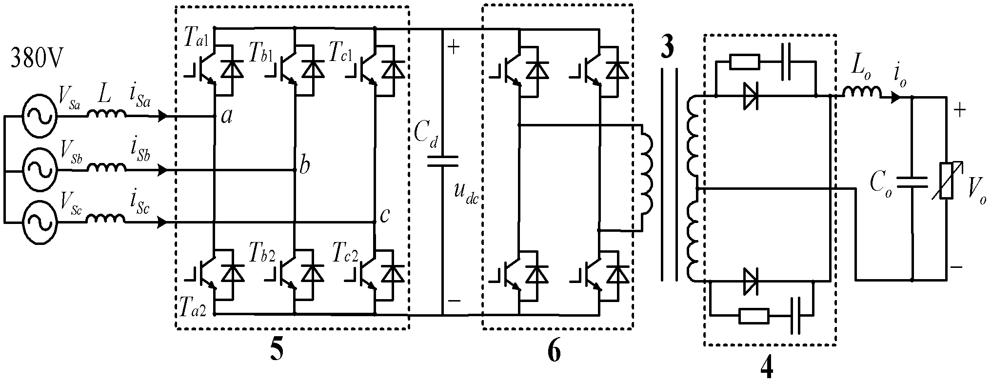
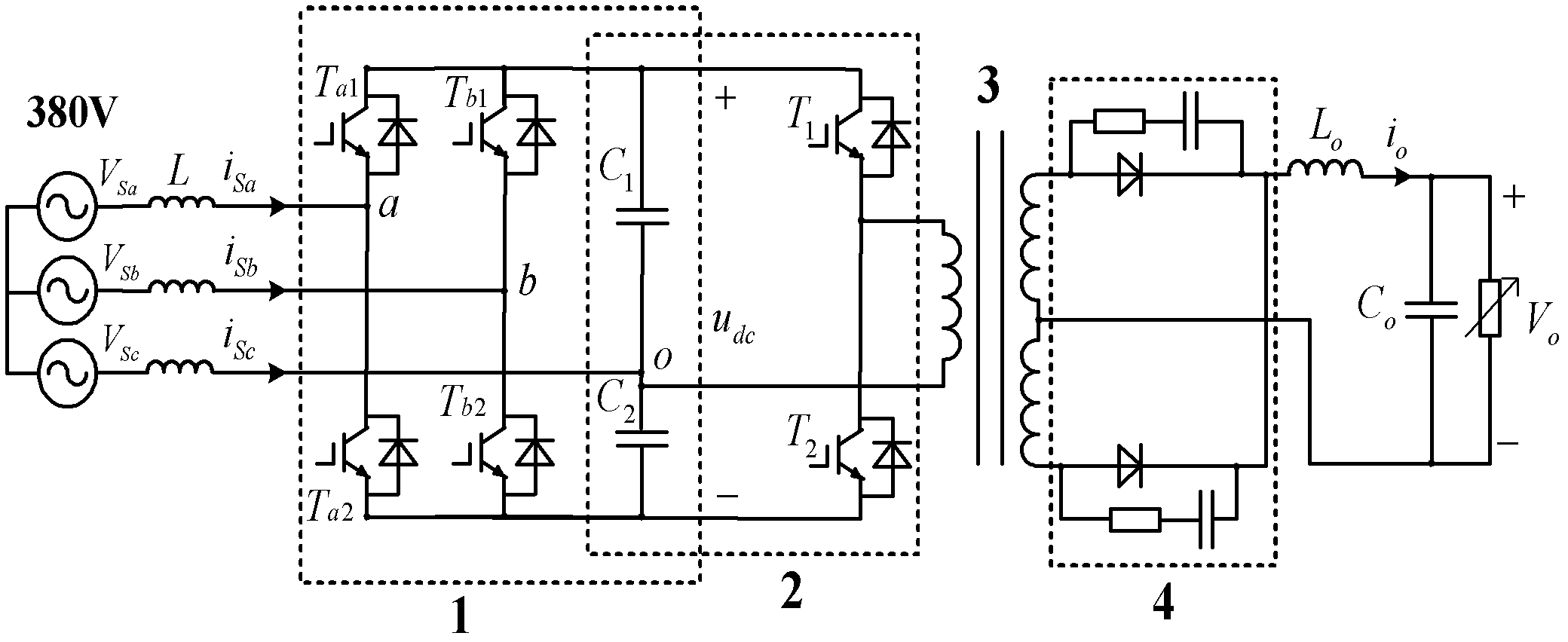
[0035] See figure 1 , Is the structure diagram of general high-power electrolytic plating high-frequency switching power supply. It includes a three-phase inverter 5, a single-phase full-bridge inverter 6, a high-frequency coupling transformer 3 and a low-voltage full-wave rectifier 4. The three-phase inverter 5 is a general voltage type inverter, which is composed of 3 switch arms, namely 6 power switches. Its AC input side is connected to the grid through a three-phase inductor L, and its DC side is connected to the grid through a capacitor C d Connect the next level circuit. In the figure, a single-phase full-bridge inverter 5, a high-frequency coupling transformer 3 and a low-voltage full-wave rectifier 4 constitute a high-frequency DC / DC converter. Among them, the single-phase full-bridge inverter 6 is a general voltage type inverter, which is composed of two switch arms, that is, four power switches.

[0036] After the three-phase alternating current is rectified by the t...


PUM


Abstract

The invention discloses a high-power simplified electrolytic and electroplating high-frequency switch power supply and a control method thereof. The simplified electrolytic and electroplating high-frequency switch power supply comprises a three-phase inverter based on three phases and two arms, and a high-frequency DC/DC converter that is formed by serially connecting a single-phase half-bridge inverter, a high-frequency coupling transformer and a low-voltage full-wave rectifier; the three-phase inverter based on the three phases and two arms is formed by connecting two switch arms and two serially-connected capacitor branches at the direct-current side in parallel; the single-phase half-bridge inverter is formed by connecting a switch arm and two serially-connected capacitor branches at the direct-current side in parallel; the three-phase inverter and the single-phase half-bridge inverter commonly share one group of direct-current side capacitors; the input terminal of the three-phase inverter is connected with a power network by a three-phase inductor L; and the output terminal of the three-phase inverter is connected with the single-phase half-bridge inverter. The switch power supply has few switch devices, small loss, high efficiency, small direct-current ripples, high response speed and small voltage distortion and current distortion. The method in the invention has the advantages of improving the response speed of the three-phase inverter and tracking the change of the load power in real time.

Description

Technical field [0001] The invention relates to a switching power supply and a control method thereof, in particular to a high-power simplified electrolytic plating high-frequency switching power supply and a comprehensive control method thereof. Background technique [0002] In the application of power electronic technology and various power supply systems, switching power supply technology is at the core. In the electric vehicle, variable frequency drive and electrolytic plating industries, it is inseparable from the switching power supply technology, through the switching power supply to change the power frequency, so as to achieve nearly ideal load matching and drive control. The traditional thyristor or diode rectifier circuit is very large and heavy. If the Gordon switching power supply technology is adopted, its volume and weight will be greatly reduced, and it can greatly improve the power utilization efficiency, save materials, reduce costs, and achieve high-efficiency e...

Claims


Application Information

Patent Timeline
IPC IPC(8): H02M7/12H02M7/219H02M3/335
Inventor 罗安马伏军谢宁张寅王刚王晓刘芸
Owner HUNAN UNIV
Why Eureka
Try Eureka