Supercharge Your Innovation With Domain-Expert AI Agents!

High-speed burner impulse tunnel furnace

A high-speed burner and tunnel furnace technology, applied in the direction of furnace, furnace type, lighting and heating equipment, etc., can solve the problems of outdated control means, small range of fuel adaptation, and reduce the temperature difference of the atmosphere, so as to enhance the convection heat transfer in the furnace, The fuel is suitable for a wide range and improves the effect of stirring

Inactive Publication Date: 2011-10-26
胡和平
View PDF4 Cites 2 Cited by
  • Summary
  • Abstract
  • Description
  • Claims
  • Application Information

AI Technical Summary

Problems solved by technology

Using this kind of ordinary burner, the ejection speed of combustion products in the furnace is low, the convective heat transfer effect is poor, the atmosphere in the furnace is not stirred well, and the temperature difference in the furnace atmosphere is reduced. The temperature atmosphere in the furnace is usually ≥±25°C
Now, tunnel furnace technology requires the atmosphere in the furnace to be controlled within ≤±10°C, which cannot be guaranteed by using ordinary burners
[0003] The combustion stability of the ordinary burner flame is poor, and the burner cannot directly burn low calorific value fuels such as blast furnace gas, resulting in a small range of fuel adaptation at low temperature
[0004] In addition, the traditional tunnel furnace generally adopts manual adjustment control, the control method is backward, and the temperature control accuracy difference is ≤±15°C
Since the heating process requires manual operation, it cannot meet the requirements of various heating processes

Method used


Image

  • High-speed burner impulse tunnel furnace
  • High-speed burner impulse tunnel furnace
  • High-speed burner impulse tunnel furnace

Examples


Embodiment Construction

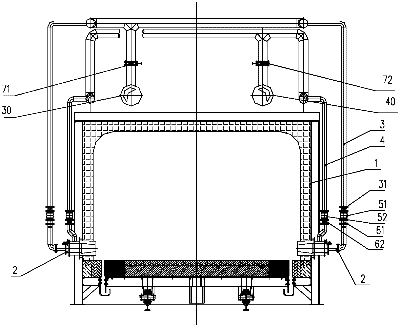
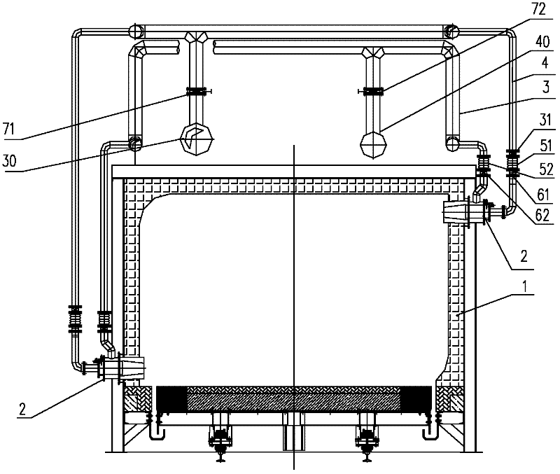
[0017] refer to figure 1 , the high-speed burner pulse tunnel furnace of the present invention comprises a furnace body 1, 2 high-speed burners 2, a gas pipeline 3, an air pipeline 4, a gas shut-off valve 31 and 2 manual regulating valves, 2 pulse control valves and a combustion control device .

[0018] Two high-speed burners 2 are installed on the lower ends of the two side walls of the furnace body 1 respectively. One end of the gas pipeline 3 is a gas inlet 30, the other end of the gas pipeline 3 communicates with the gas inlet of the high-speed burner 2, one end of the air pipeline 4 is an air inlet 40, and the other end of the air pipeline 4 communicates with the air inlet of the high-speed burner 2.

[0019] The first manual regulating valve 61 is installed on the gas pipeline 3 before the high-speed burner 2 , and the second manual regulating valve 62 is installed on the air pipeline 4 before the high-speed burner 2 . The gas shut-off valve 31 is installed on the gas...


PUM


Abstract

The invention discloses a high-speed burner impulse tunnel furnace which comprises a furnace body, a fuel gas pipeline, an air pipeline, a fuel gas cutting valve, two high-speed burners, two manual regulating valves, two impulse control valves and a combustion control device, wherein the two high-speed burners are installed at the lower end of two side walls of the furnace body or are installed at the upper end and the lower end of the two side walls of the furnace body; the impulse control valve and the fuel gas cutting valve are electrically connected with the combustion control device; and the combustion control device is an impulse regulating device or an upper computer. The furnace has the advantages that: the convection heat transfer in the furnace is strengthened, the atmosphere stirring in the furnace is improved, the atmosphere temperature difference in the furnace is reduced, and the atmosphere in the furnace can be controlled to be less than or equal to + / - 10 DEG C. The high-speed burner can directly burn fuel with low heating value such as blast-furnace gas, and the fuel is widely applicable. Impulse regulation is adopted to control temperature in the heating process, and various heating requirements can be met; and when an upper machine sets a temperature control curve, the furnace can be full-automatically controlled without manual operation, and the temperature control accuracy can reach less than or equal to + / - 1 DEG C.

Description

technical field [0001] The invention relates to combustion furnace equipment, in particular to a high-speed burner pulse tunnel furnace. Background technique [0002] At present, the tunnel furnace adopts conventional ordinary burners. Using this kind of ordinary burner, the ejection speed of combustion products in the furnace is low, the convective heat transfer effect is poor, the atmosphere in the furnace is not stirred well, and the temperature difference in the furnace atmosphere is reduced. The temperature atmosphere in the furnace is usually ≥±25°C. Now, tunnel furnace technology requires that the atmosphere in the furnace be controlled within ≤±10°C, which cannot be guaranteed by using ordinary burners. [0003] The combustion stability of the ordinary burner flame is poor, and the burner cannot directly burn low calorific value fuels such as blast furnace gas, resulting in a small range of fuel adaptation at low temperature. [0004] In addition, the traditional t...

Claims


Application Information

Patent Timeline
IPC IPC(8): F27B9/36F27B9/40
Inventor 胡和平
Owner 胡和平
Features
  • R&D
  • Intellectual Property
  • Life Sciences
  • Materials
  • Tech Scout
  • Unparalleled Data Quality
  • Higher Quality Content
  • 60% Fewer Hallucinations
Learn More