Longitudinal veneer slicer

A slicing machine and veneer technology, which is applied in the direction of manufacturing flat surface processing machines, wood processing appliances, manufacturing tools, etc., can solve the problems of difficulty, high investment cost, complex structure, etc., achieve good level stability, reduce labor The effect of high volume, good operation safety

Inactive Publication Date: 2011-11-02
丁占科
View PDF12 Cites 6 Cited by
  • Summary
  • Abstract
  • Description
  • Claims
  • Application Information

AI Technical Summary

Problems solved by technology

[0003] However, most of the existing vertical veneer slicers have certain difficulties for some small and medium-sized enterprises due to their complex structure, large volume, and high investment costs, an

Method used


Image

  • Longitudinal veneer slicer
  • Longitudinal veneer slicer
  • Longitudinal veneer slicer

Examples


Embodiment 1

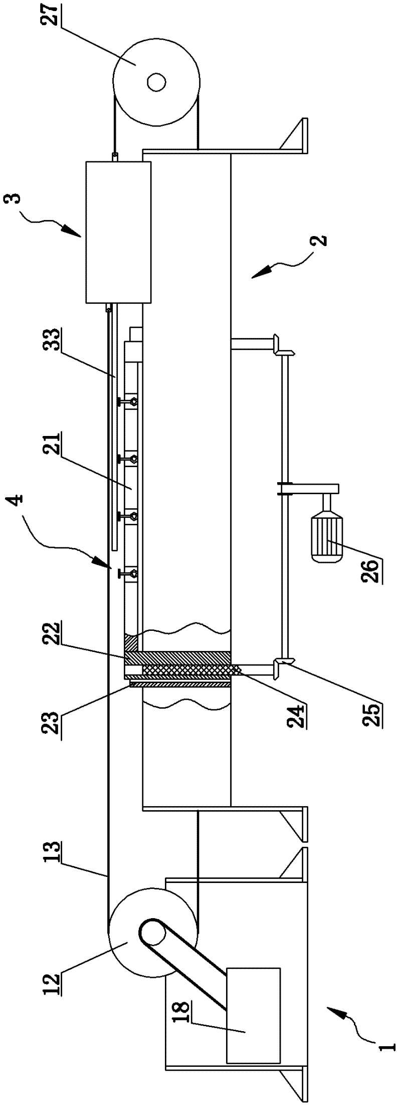
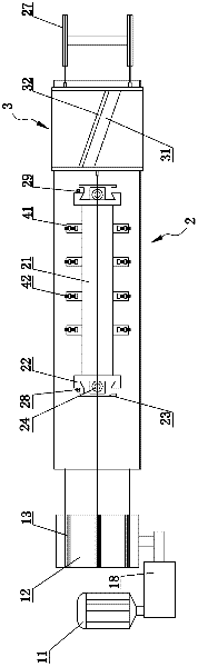
[0031] Such as figure 1 and figure 2 Commonly shown is an embodiment of a vertical veneer planer, which includes a main frame 2, a sub-frame 1, and a knife rest 3 that slides along the longitudinal direction of the main frame 2. A planer 32 is provided on the knife holder 3 .

[0032] The main frame 2 is horizontally provided with a workbench 21, and at the same time, guide rails 23 are vertically fixed at the two ends of the workbench 21 on the main frame 2, and a lifting slide 22 is slid in the guide rail 23. The workbench 21 is fixed between the upper ends of the two lifting slides 22. When the vertical veneer planer is working, the workbench 21 supports wood, and is arranged on the The clamping devices 4 on both sides of the workbench 21 fix the wood, so that when the lifting slide 22 slides upward for a certain distance, the workbench 21 can follow the upward movement for a certain distance, and at the same time, the tool rest 3 Sliding over the workbench 21, the plan...

Embodiment 2

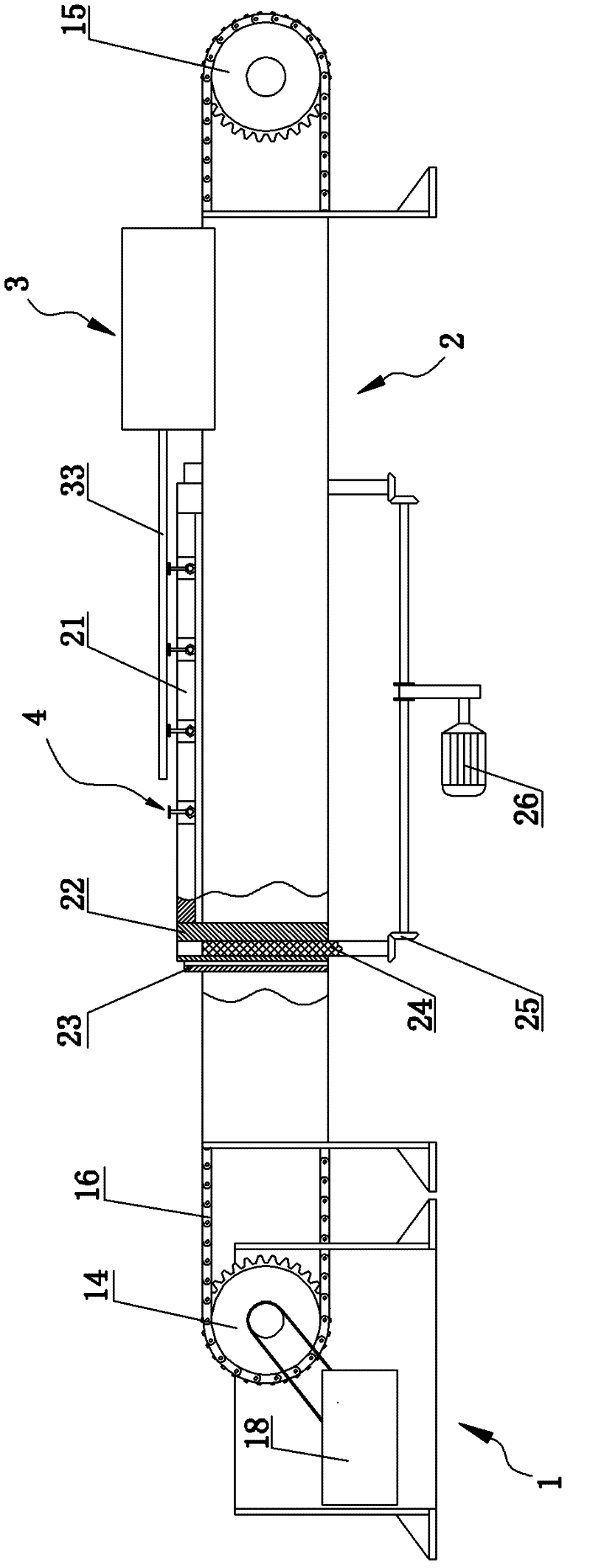
[0045] Such as image 3 and Figure 4 Commonly shown is another embodiment of the vertical veneer cutter, the difference between this embodiment and embodiment one is:

[0046] The transmission device used by the drive motor 11 to drive the knife rest 3 is different. The transmission device here includes a driving sprocket 14 arranged on the sub-frame 1. The driving sprocket 14 is two and passes through A connecting shaft 17 is fixed as a whole, and two corresponding driven sprockets 15 are arranged symmetrically at the end of the main frame 2 away from the sub-frame 1, and the driving sprocket 14 and the corresponding driven sprocket 15 are Chains 16 are wound around respectively to form an upper chain and a lower chain, and the lower end of the knife rest 3 is fixedly connected to the upper chain, where the knife rest 3 and the upper chain can be directly welded and fixed as one, or the The lower end of the knife rest 3 is processed into a structure compatible with the upp...


PUM


Abstract

The invention discloses a longitudinal veneer slicer applied in the field of wood machining machinery. The longitudinal veneer slicer comprises a main frame, a secondary frame and a tool rest arranged on the main frame and capable of sliding along the longitudinal direction of the main frame, wherein the secondary frame is arranged at one end of the main frame, and a driving motor capable of driving the tool rest to reciprocate is arranged on the secondary frame; in addition, a liftable workbench is horizontally arranged on the main frame, the workbench is driven by a lifting motor, and corresponding clamping devices for clamping wood are arranged at two sides of the workbench; and when the longitudinal veneer slicer works, the wood is fixed on the workbench by using the clamping devices,the tool rest continuously reciprocates under the drive of the driving motor, meanwhile, the workbench can ascend for a distance after a slicing period is finished, and a planing tool arranged on thetool rest can continuously slice the veneer of certain thickness. The longitudinal veneer slicer has simple structure and relatively low cost, can ensure the uniformity of the thickness of the slicedveneer during slicing, and is very suitable for medium and small enterprises to use.

Description

technical field [0001] The invention relates to the field of wood processing machinery, in particular to a longitudinal veneer planer. Background technique [0002] At present, the longitudinal veneer planer is the main equipment for the production of wood veneer and micro-veneer. According to the movement direction of the planer relative to the horizontal plane, the longitudinal veneer planer can be divided into two categories: vertical and horizontal; according to The planing direction is vertical or parallel to the length direction of the wood fiber, and the longitudinal veneer planer can be divided into a horizontal planer and a longitudinal planer. [0003] However, most of the existing vertical veneer slicers have certain difficulties for some small and medium-sized enterprises due to their complex structure, large volume, and high investment costs, and their sliced ​​thickness and width cannot be produced according to needs. , has certain limitations in use, which al...

Claims


Application Information

Patent Timeline
IPC IPC(8): B27C1/00
Inventor 丁占科丁国华丁秀明
Owner 丁占科
Why Eureka
Try Eureka